Chapter G - PARTS REPLACEMENT & REPAIR
Planmeca Compact i G-43
OTHER PARTS REPLACEMENT
Technical Manual
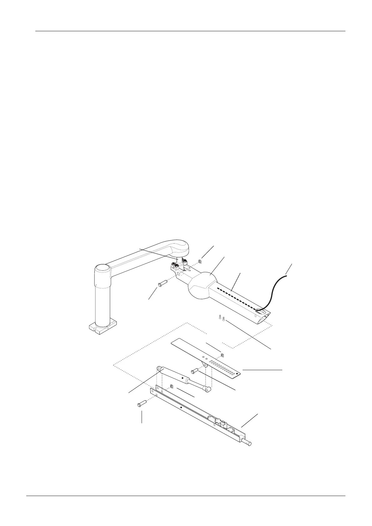
9.2 Replacing OP delivery arm gas spring
NOTE Please note that the console arm cable need not to be removed during this
operation.
a) Release the tension of the gas spring (i.e. decrease the tension as much as possible) as
described in section 1.3 “Adjusting balance of the OP delivery arm” on page F-3.
b) Remove the instrument console and the lower joint axle as described in section 9.1
“Detaching the instrument console from the OP delivery arm” on page G-42.
c) Slide the arm joint cover from over the upper joint.
d) Unscrew the two M5x8 DIN 7991 screws from under the lifting arm.
e) Lift the console arm to its upmost position. Remove the ø10 DIN 6799 securing ring from the
upper joint pin and tap off the upper joint pin from the upper joint axle.
f) Remove the whole lifting arm assembly from inside the lifting arm.
g) Remove ø10 DIN 6799 securing ring from the gas spring pin and remove the gas spring pin.
h) Remove the ø10 DIN 6799 securing ring from the upper joint pin at the other end of the gas
spring and remove the upper joint pin.
i) Install the new gas spring in reverse order.
j) Adjust the balance of the instrument console as described in section 1.4 “Adjusting angle of
the OP delivery arm instrument console” on page F-9.
k) Adjust the balance of the console arm as described in section 1.3 “Adjusting balance of the
OP delivery arm” on page F-3.
Arm joint cover
M5x8 DIN 7991
Lifting arm
Upper joint pin
Upper joint axle
Lifting arm assembly
Gas spring pin
Upper joint pin
Gas spring
ø10 DIN 6799
ø10 DIN 6799
Console arm cable
ø10 DIN 6799
Adjustment plate