EasyManuals Logo

Planmeca Compact I User Manual

Planmeca Compact I
244 pages
To Next Page IconTo Next Page
To Previous Page IconTo Previous Page
Page #195 background imageLoading...
Page #195 background image
Planmeca Compact i H-1
Chapter
Technical Manual
H
FOOT CONTROL
1 PARTS REPLACEMENT & REPAIR
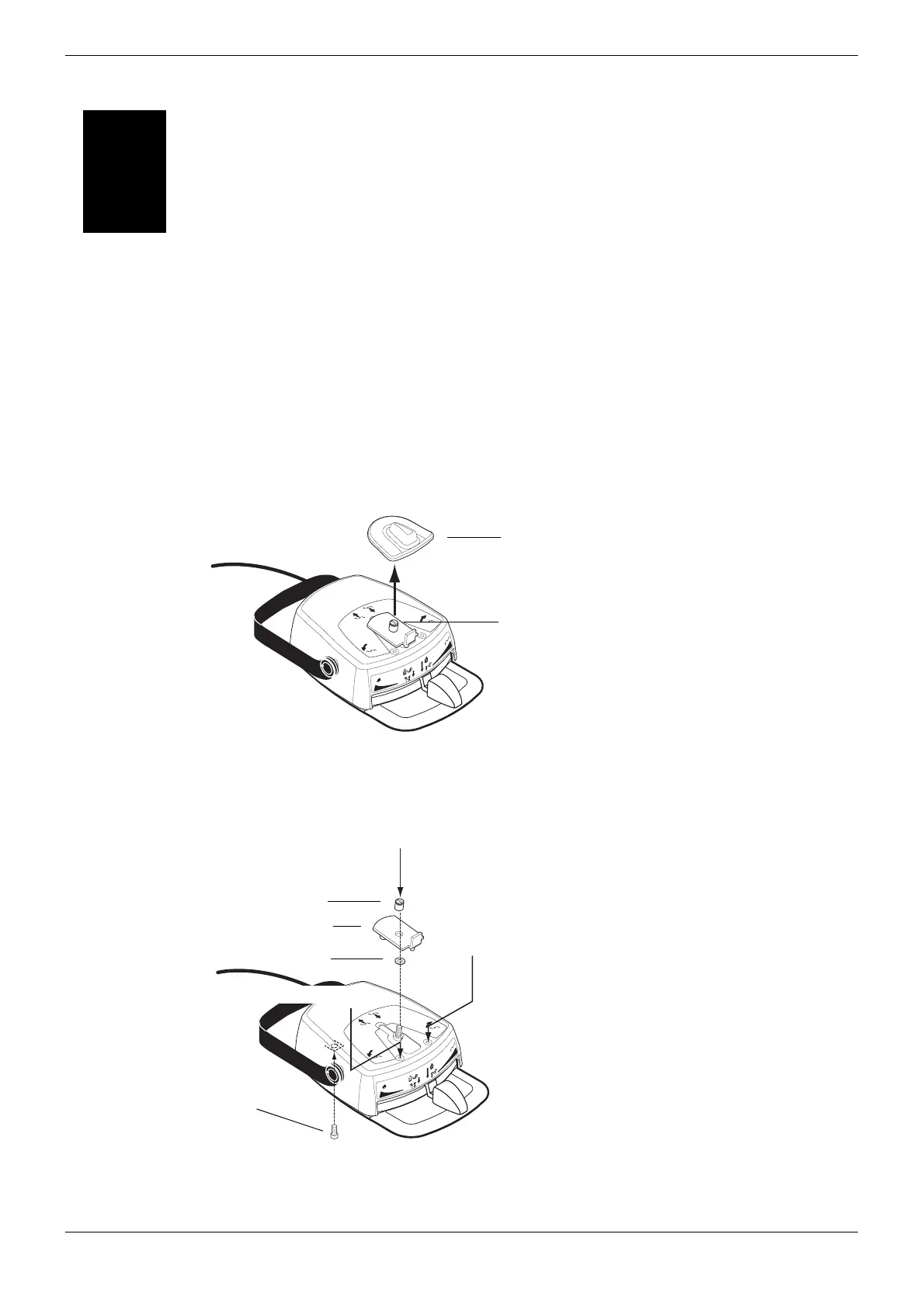
1.1 Removing foot control cover
a) Detach the chair control cover knob.
b) Unscrew the knob holder with a screwdriver and remove the knob support. Be careful not to
lose the spacer located on the underside of the knob support.
c) Unscrew the M4x8 DIN 7984 screw from under the foot control and the two M4x10 DIN 7991
screws from the top.
S
Fcntrlknob0199.eps
A B
CD
Cover knob
Knob holder
S
Fcntrlcover0199.eps
A B
CD
M4x8 DIN 7984
M4x10 DIN 7991
Knob support
Knob holder
Spacer
M4x10 DIN 7991

Table of Contents

Questions and Answers:

Question and Answer IconNeed help?

Do you have a question about the Planmeca Compact I and is the answer not in the manual?

Planmeca Compact I Specifications

General IconGeneral
SpittoonYes
Operating LightLED
Imaging TechnologyDigital
X-ray Tube Voltage60-70 kV
X-ray Tube Current7 mA
Focal Spot Size0.8 mm
Exposure Time Range3.2 s
Power Supply50/60 Hz

Related product manuals