Chapter H - FOOT CONTROL
H-10 Planmeca Compact i
ADJUSTMENTS
Technical Manual
2.4 Adjusting height of the foot control pedal (old foot control
model, serial number smaller than 826740)
a) Remove the foot control cover as described in section “Removing foot control cover” on page
H-1.
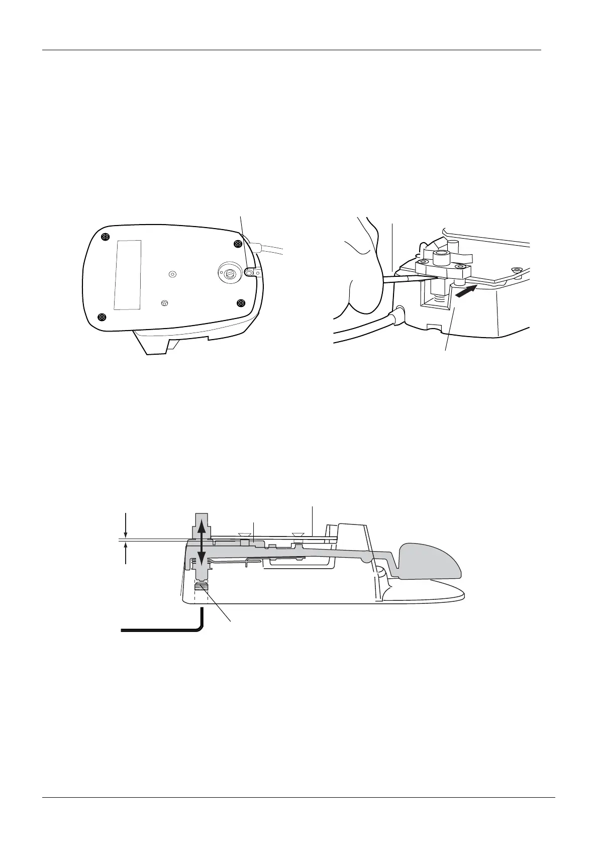
b) Loosen the pedal height adjuster on the underside of the foot control a couple of turns.
c) Insert a screwdriver between the pedal and the bearing bar and slide the pedal downwards
along the pedal axle.
d) Apply a drop of Loctite 243 sealer (or corresponding) to the pedal height adjuster. Using a
feeler gauge, adjust the clearance between the foot control PCB and the pedal’s sector plate
to 0.5 - 1mm by tightening the pedal height adjuster. Do not allow Locktite to get to the pedal
axle.
NOTE Make sure that the sector plate does not touch the foot control PCB in any
pedal position.
Check also that the pedal does not touch the switch on the underside of the
PCB.
e) Reassemble the foot control in reverse order.
f) Calibrate the foot control as described in section “Calibrating foot control” on page H-15.
Adjpedalheight.eps
Pedal height adjuster
Measure the clearance
between PCB and casting.
Slide the pedal downwards
using a screwdriver.
Adjpedal.eps
0.5-1mm
Foot control PCB
Sector plate
Pedal height adjuster