Chapter H - FOOT CONTROL
Planmeca Compact i H-17
ADJUSTMENTS
Technical Manual
2.7 Adjustments and functional check-ups after parts
replacements
• Center the foot control pedal by adjusting the position of the pedal centering plate. (See page H-7.)
• Eliminate the horizontal play of the pedal by slightly turning the adjusting rod from the underside of the
foot control. (See page H-8.)
• Adjust the tension and angle of the pedal by tightening/loosening the tension adjusting screw and the
angle adjusting screw. (See page H-9.)
• Adjust the height of the pedal in a way that the air gap between pedal’s sector plate and the foot control
PCB is 0,5-1mm. (See page H-11.)
• Calibrate the foot control. (See page H-15.)
In case of error (if re-calibration does not help):
• Check the chair control signals in the service mode #61
the four last segments refer to the positions A, B, C and D
• Check the pedal horizontal coordinate in the service mode #62
when pedal is in center position, the display must show “0”
when pedal moved fully right or left, the display must show +-255
pedal must be able to be moved 5mm from max. before the display changes from +-255
• Check the pedal vertical coordinate in the service mode #63
when pedal is in rest, the display must show 50...70
when pedal is pressed down, the display must show -50...-70
• Check the signal level of the capacitance sector A in the service mode #64
when the pedal is in rest, the display must show 3000...7000
(<3000 = air gap too big, >7000 = air gap too small)
when the pedal is fully right or left, the display must differ at least +-600
if not, air gap too big or pedal’s sector plate is tilted
• Check the signal level of the capacitance sector B in the service mode #65
the display must not differ more than +-300 from the above when the pedal is in rest
if more, the pedal’s sector plate is tilted
when the pedal is fully right or left, the display must differ at least +-600
if not, air gap too big or pedal’s sector plate is tilted
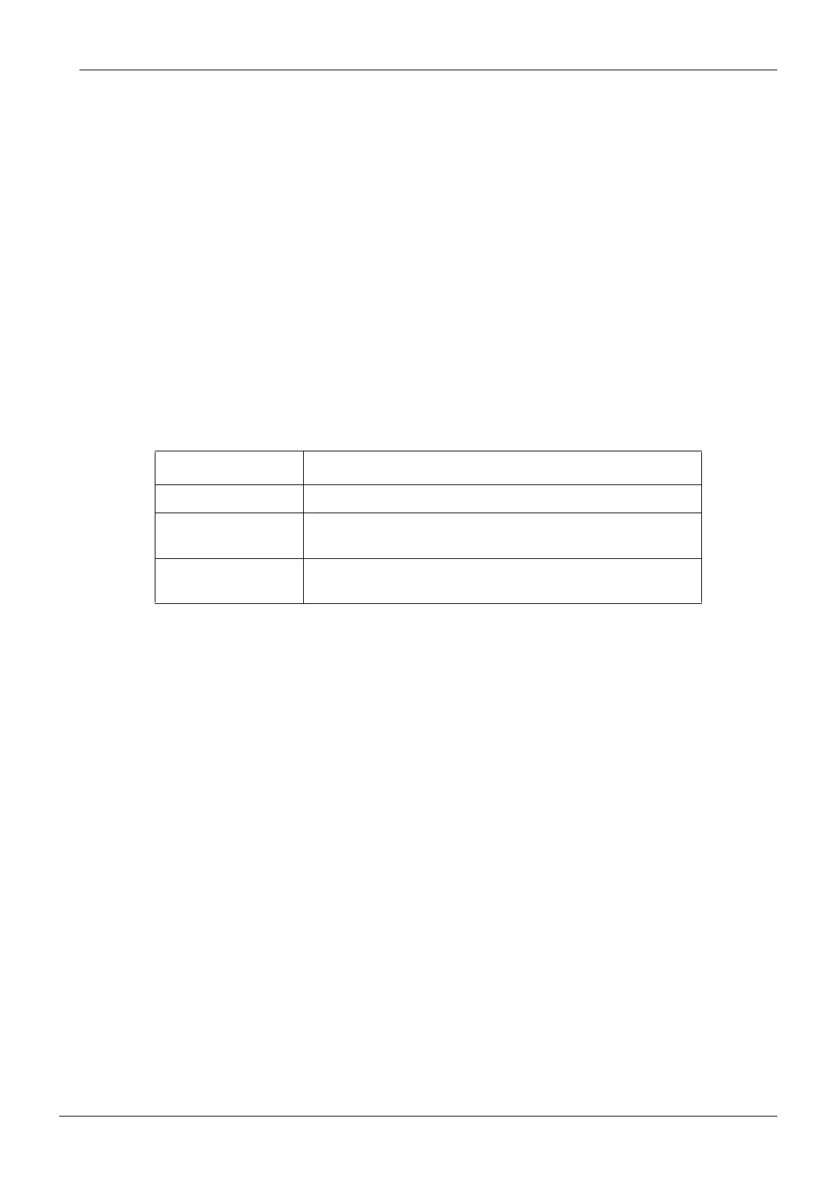
ERROR MESSAGE REMEDY
E54.1 or E54.2 replace the foot control PCB
E54.3 ... E54.7 re-adjust the air gap between pedal’s sector plate and PCB
re-adjust the horizontality of the pedal’s sector plate
E54.8 re-adjust the air gap between pedal’s sector plate and PCB
replace the foot control PCB