Chapter G - PARTS REPLACEMENT & REPAIR
G-20 Planmeca Compact i
ELECTRICAL PARTS REPLACEMENT
Technical Manual
5 ELECTRICAL PARTS REPLACEMENT
5.1 How to replace/upgrade the software
WARNING
Always turn the unit off before removing the software chip from its socket.
Never turn the unit on if the software chip is not in its socket.
NOTE Antistatic precautions must be performed when handling the software chip.
Touch any grounded metal part of the unit before touching the software chip.
NOTE The software is always downwards compatible i.e. a new software is always
compatible with an older unit. However, replacing e.g. a foot control to an older
unit may cause some software incompatibilities.
a) Turn off the unit from the mains switch.
b) Remove the cover of the electronics control box as described in section 5.3 “Replacing main
control PCB” on page G-22.
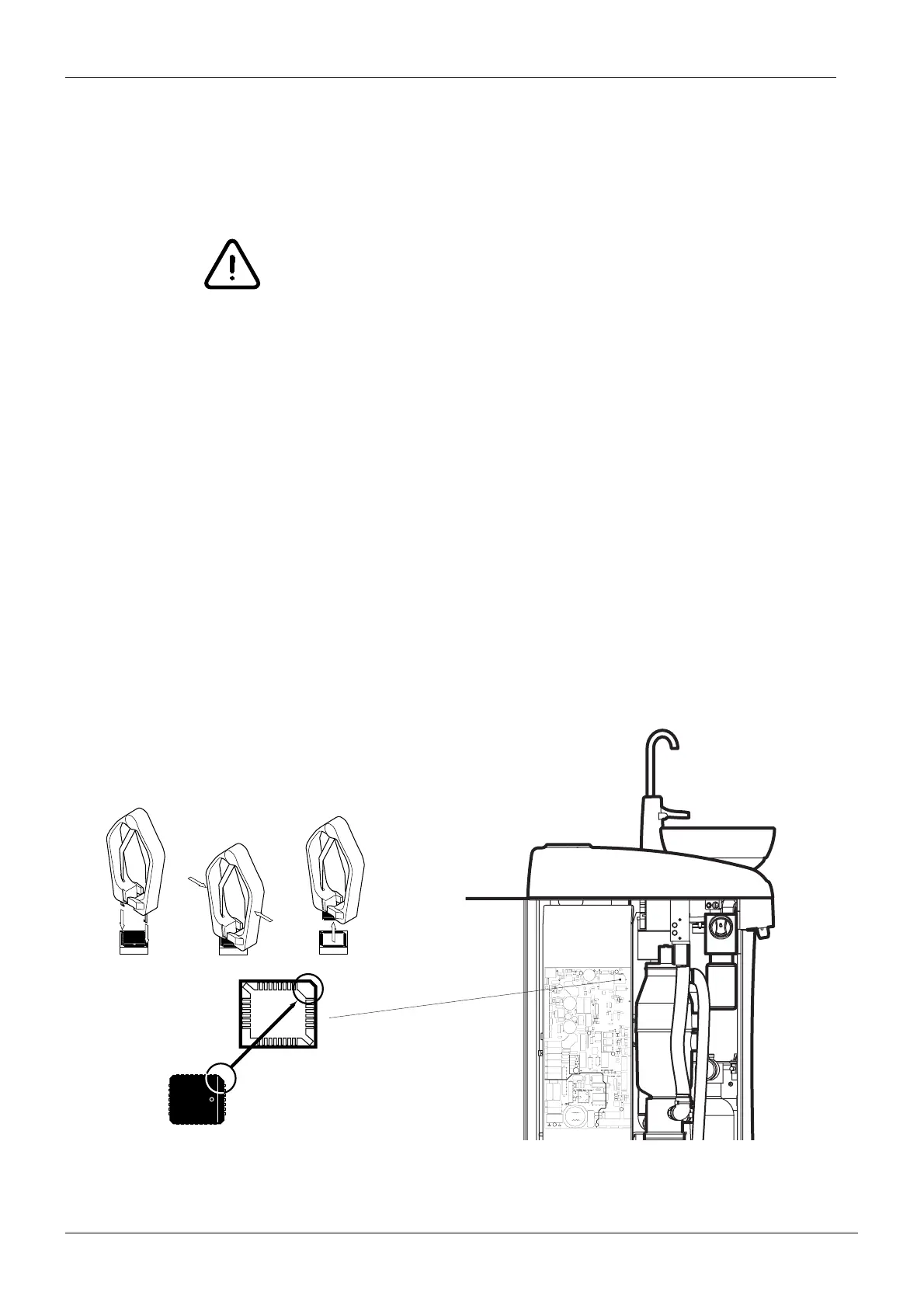
c) Remove the software chip from its socket with the special tool as illustrated below.
NOTE The orientation of the software chip is critical. Never try to force the chip into
the socket.
d) Carefully place the new software chip into the socket.
e) Assemble the cover of the electronics control box back to its position.