Chapter G - PARTS REPLACEMENT & REPAIR
Planmeca Compact i G-35
MOTORS REPLACEMENT
Technical Manual
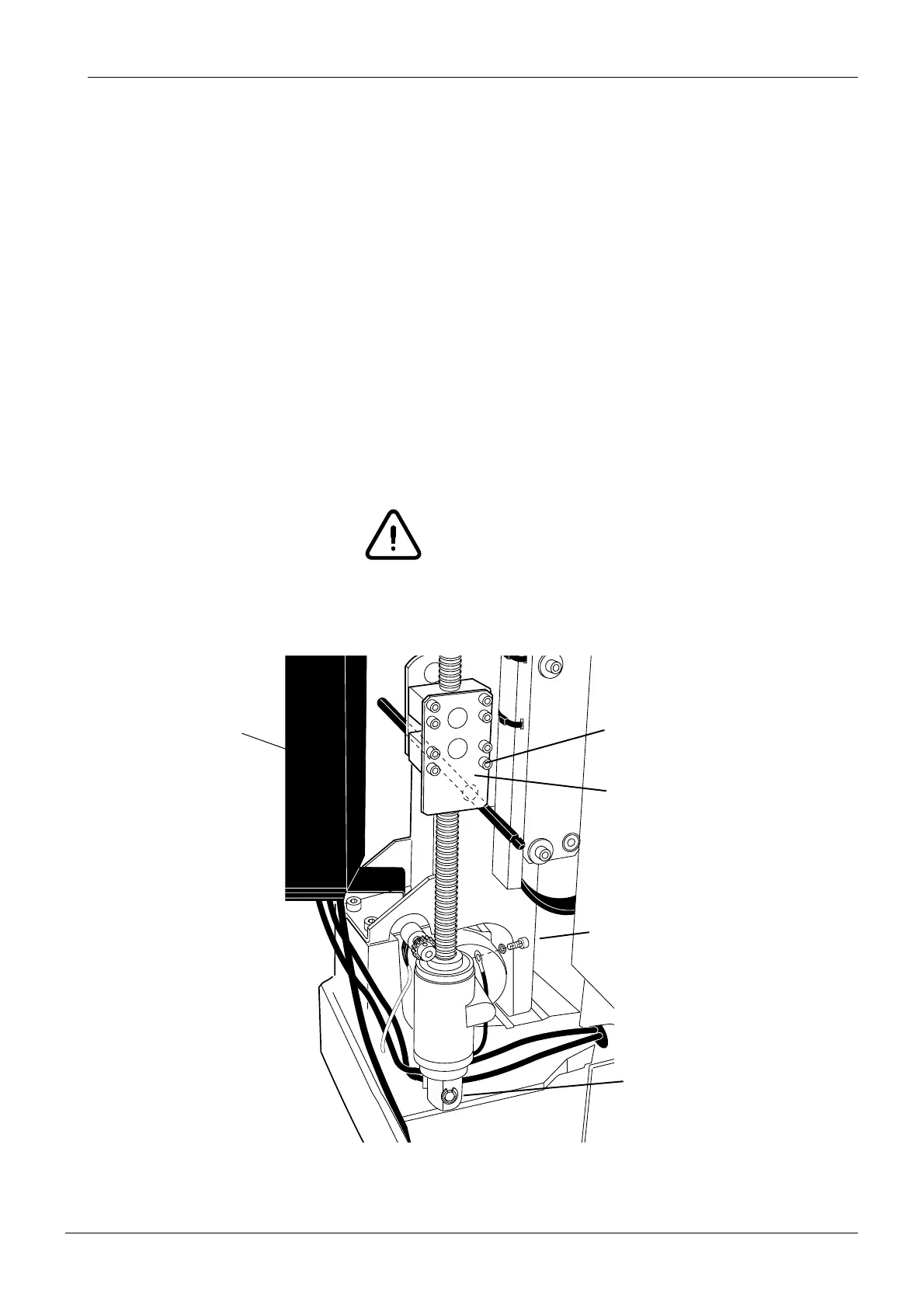
k) Unscrew the eight M6x45 DIN 912 screws that hold the nut attachment plate in position.
l) Remove the nut attachment plate and the lifting frames.
m) Remove the ø10 DIN 6799 locking ring from the lift motor attachment axle.
n) Slide the lift motor from the attachment axle and turn it in a way that the Motor grounding
cable can be detached. Detach the Motor grounding cable from the side of the motor.
o) Lift the Lift motor from the cuspidor.
p) Unscrew the M10x25 ULS screw from the end of the worm screw and remove the worm
screw nut.
q) Detach the lift motor position sensor by unscrewing the two M5x12 DIN 7500 screws.
r) Grease the new motor’s worm screw. Install the new lift motor in reverse order.
NOTE Pay attention when reconnecting the lift motor position sensor, refer to section
5.8 “Replacing position sensors” on page G-26.
NOTE Calibrate the lift motor position sensor as described in section 2.2 “Calibrating
lift motor position sensor” on page F-20.
Unscrew the eight screws
Ensure that the steel bar
is supporting the whole
weight of the chair!
Remove the nut attachment plate
and the lifting frames
Remove the locking ring
Detach the grounding cable
Electronics
control box
lifted aside