9
9850067 R01 - 2020-2021 GENERAL / GENERAL XP Service Manual
© Copyright Polaris Inc.
9.31
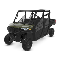
4. Insert upper control arm ball joint end into the bearing
carrier. Install upper ball joint pinch bolt
t
into the
bearing carrier and torque bolt to specification.
TORQUE
Ball Joint Pinch Bolts:
42 lb-ft (57 Nm)
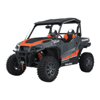
5. Install brake line mounting brackets
y
.
6. Attach shock to control arm with fastener. Torque
lower shock bolt to specification.
TORQUE
Shock Mount Fasteners:
20 lb-ft (27 Nm) + 90°
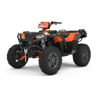
7. Attach stabilizer link to control arm with fastener.
Torque to specification
TORQUE
Stabilizer Bar Link Fastener:
42 lb-ft (57 Nm)
8. Install NEW ball joint into control arm. Refer to “Ball
Joint Installation” page 9.52 procedure.
STEERING / SUSPENSION
 Loading...