Remote control basics
R&S
®
NRPxxS(N)
155User Manual 1177.5079.02 ─ 15
1
Device status
2
Questionable status
3
Standard event status
4
Operation status
5
Error queue
Message queue
Status byte
1
0
2
3
MAV
ESB
RQS/MSS
7
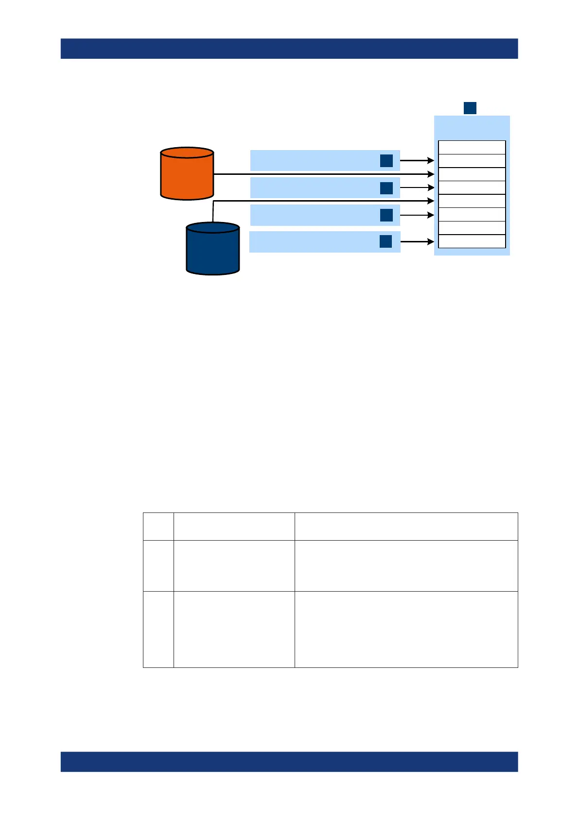
Figure 11-1: Status registers overview
1 = Status byte, see Table 11-3
2 = Chapter 11.2.2, "Device status register", on page 157
3 = Chapter 11.2.3, "Questionable status register", on page 158
4 = Chapter 11.2.4, "Standard event status and enable register (ESR, ESE)", on page 161
5 = Chapter 11.2.5, "Operation status register", on page 162
The highest level is formed by the status byte register (STB) and the associated ser-
vice request enable (SRE) register.
The status byte register (STB) receives its information from:
●
Standard event status register (ESR)
●
Associated standard event status enable register (ESE)
●
SCPI-defined operation status register
●
Questionable status register, which contains detailed information on the device.
Table 11-3: Used status byte bits and their meaning
Bit
no.
Short description Bit is set if
1 Device status register summary A sensor is connected or disconnected or when an error has
occurred in a sensor, depending on the configuration of the
sensor status register.
Chapter 11.2.2, "Device status register", on page 157.
2 Error queue not empty The error queue has an entry. If this bit is enabled by the ser-
vice request enable register, each entry of the error queue
generates a service request. An error can thus be recognized
and specified in detail by querying the error queue. The query
yields a conclusive error message. This procedure is recom-
mended since it considerably reduces the problems of IEC/
IEEE-bus control.
Status reporting system

 Loading...

