Remote control basics
R&S
®
NRPxxS(N)
166User Manual 1177.5079.02 ─ 15
0
1
2
3
4
5
6
7
8
9
10
11
12
13
14
15
0
Sensor waiting for trigger
0
0
0
0
0
0
0
0
0
0
0
0
0
0
+
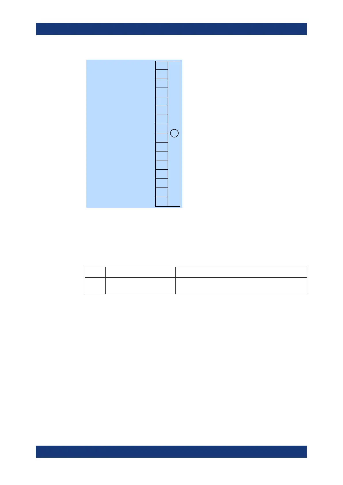
Figure 11-10: Operation trigger status register
Querying the register:
●
STATus:OPERation:TRIGger:CONDition?
●
STATus:OPERation:TRIGger[:SUMMary][:EVENt]?
Table 11-12: Used operation trigger status bits and their meaning
Bit no. Short description Bit is set if
1 Sensor waiting for trigger Sensor is waiting for a trigger event. When the trigger event
occurs, the sensor changes into the measuring state.
11.2.5.4 Operation sense status register
The CONDition register contains information whether a power sensor is being initial-
ized. The EVENt register contains information whether an initialization was started or
completed since the last query.
A power sensor is initialized if:
●
Supply voltage is switched on (power-up).
●
Sensor was connected.
●
Reset was performed using:
– *RST
– SYSTem:PRESet
Status reporting system

 Loading...

