EasyManuals Logo

R&S NRP Series User Manual

R&S NRP Series
185 pages
To Next Page IconTo Next Page
To Previous Page IconTo Previous Page
Page #169 background imageLoading...
Page #169 background image
Remote control basics
R&S
®
NRPxxS(N)
169User Manual 1177.5079.02 ─ 15
0
1
2
3
4
5
6
7
8
9
10
11
12
13
14
15
0
Upper limit fail
0
0
0
0
0
0
0
0
0
0
0
0
0
0
+
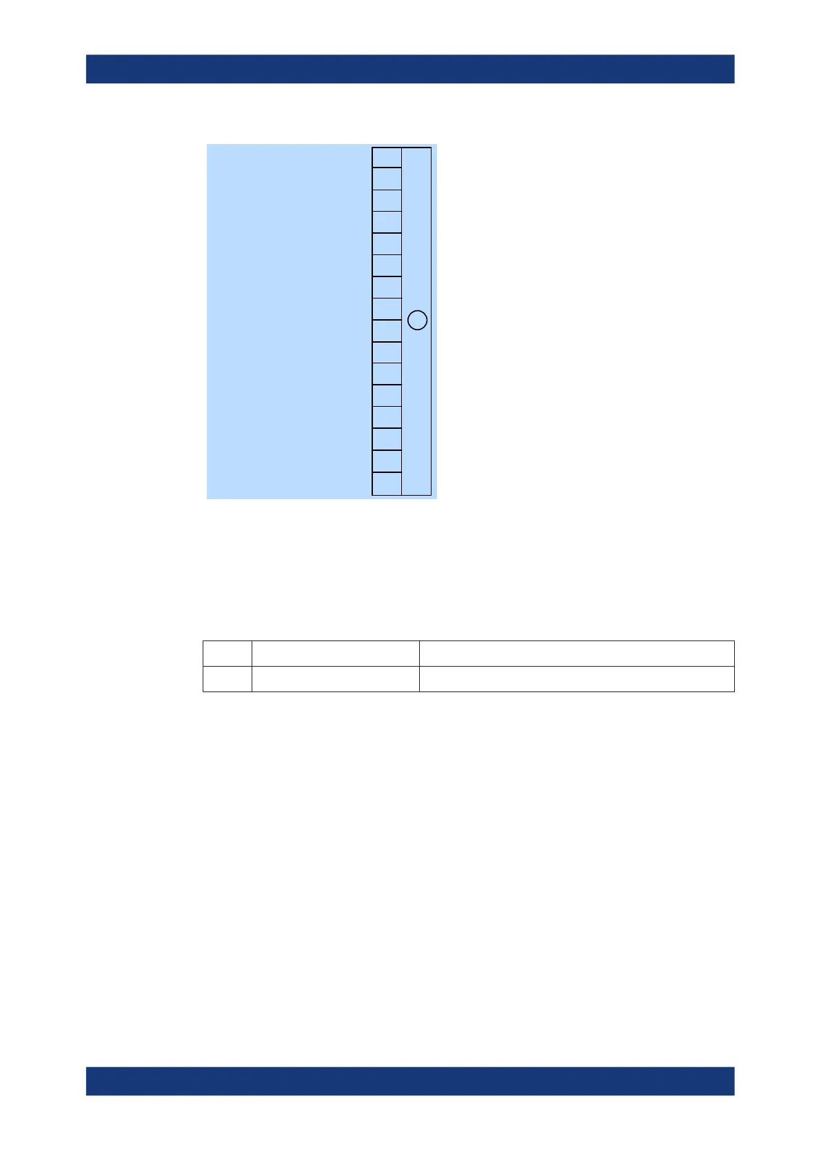
Figure 11-13: Operation upper limit fail status registers
Querying the register:
STATus:OPERation:ULFail:CONDition?
STATus:OPERation:ULFail[:SUMMary][:EVENt]?
Table 11-15: Used operation upper limit fail status bits and their meaning
Bit no. Short description Bit is set if
1 Upper limit fail Measured value exceeds the upper limit value.
Status reporting system

Table of Contents

Other manuals for R&S NRP Series

Questions and Answers:

Question and Answer IconNeed help?

Do you have a question about the R&S NRP Series and is the answer not in the manual?

R&S NRP Series Specifications

General IconGeneral
Product TypePower Sensor
Connector TypeSMA, 3.5 mm, 2.4 mm
InterfaceUSB, LAN
Storage Temperature-40°C to +70 °C
DimensionsDependent on model
WeightDependent on model
CompatibilityR&S Instruments
TypeDiode

Related product manuals