Preparing for use
R&S
®
NRPxxS(N)
23User Manual 1177.5079.02 ─ 15
5. Connect the controlling host to the non-PoE Ethernet switch.
6. Establish a connection between the power sensor and the network.
See Chapter 3.7.3.2, "Establishing a connection to the network", on page 23.
Setup with a PoE injector
HOST
INTERFACE
IN: 3 V or 5 V logic
OUT: min. 2 V into 50 Ω
max. 5.3 V
TRIG2
I/0
PoE
SMART SENSOR TECHNOLOGY
NRP
2 3 4
5
6
7
8
1
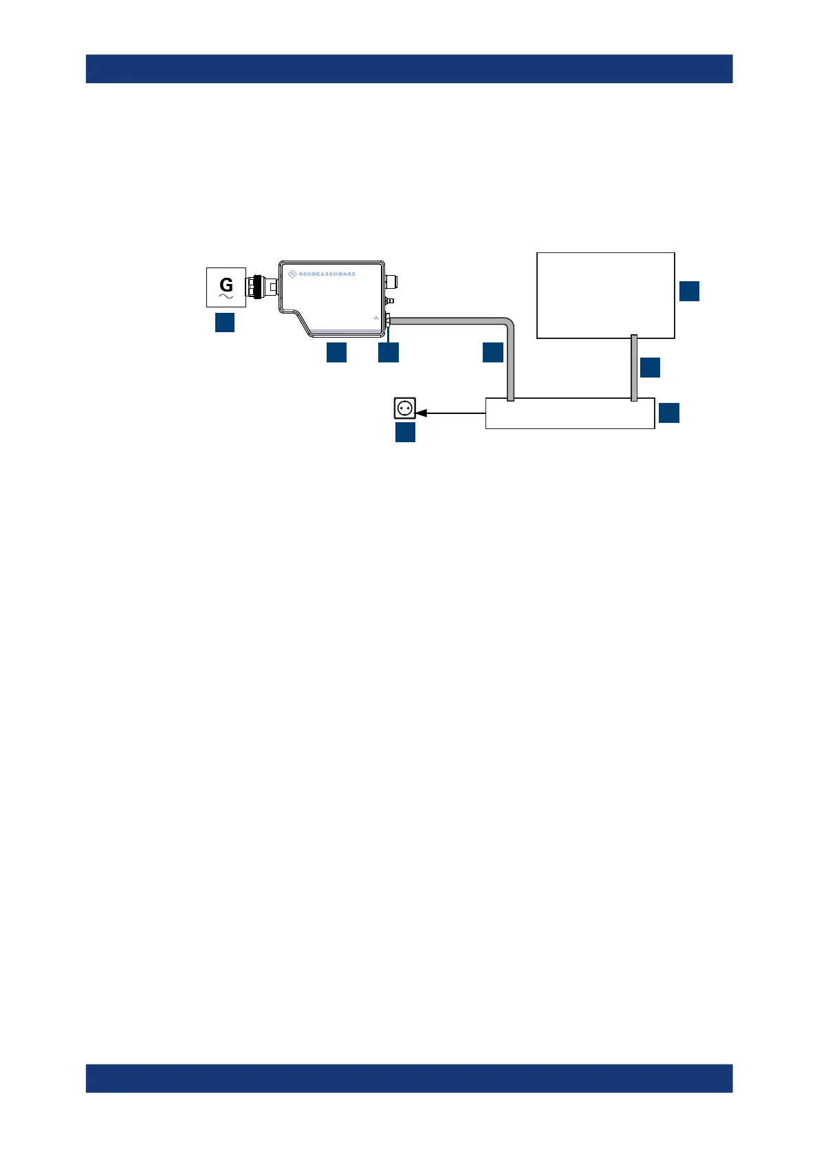
Figure 3-5: Setup with a PoE injector
1 = Signal source
2 = LAN power sensor
3 = RJ-45 Ethernet connector
4, 6 = RJ-45 Ethernet cable
5 = Controlling host
7 = PoE injector
8 = AC supply
1.
NOTICE! Incorrectly connecting or disconnecting the power sensor can damage
the power sensor or lead to erroneous results. Ensure that you connect or discon-
nect the power sensor as described in Chapter 3.4, "Connecting to a DUT",
on page 15.
Connect the power sensor to the signal source.
2.
NOTICE! Risk of sensor damage. Only use PoE power sourcing equipment (PSE)
as described in "Choose the PoE power sourcing equipment (PSE) with care"
on page 17.
Connect the RJ-45 Ethernet connector of the sensor to the output of the PoE injec-
tor.
3. Connect the PoE injector to a power supply.
4. Connect the controlling host to the input of the PoE injector.
5. Establish a network connection between the power sensor and the controlling host.
3.7.3.2 Establishing a connection to the network
There are two methods to establish a network connection:
●
Power sensor and controlling host are connected to a common network
(infrastructure network).
Connecting to a controlling host

 Loading...

