Operating concepts
R&S
®
NRPxxS(N)
35User Manual 1177.5079.02 ─ 15
Setup
3
1
2 4
6
HOST
INTERFACE
IN: 3 V or 5 V logic
OUT: min. 2 V into 50 Ω
max. 5.3 V
TRIG2
I/0
PoE
SMART SENSOR TECHNOLOGY
NRP
5
7
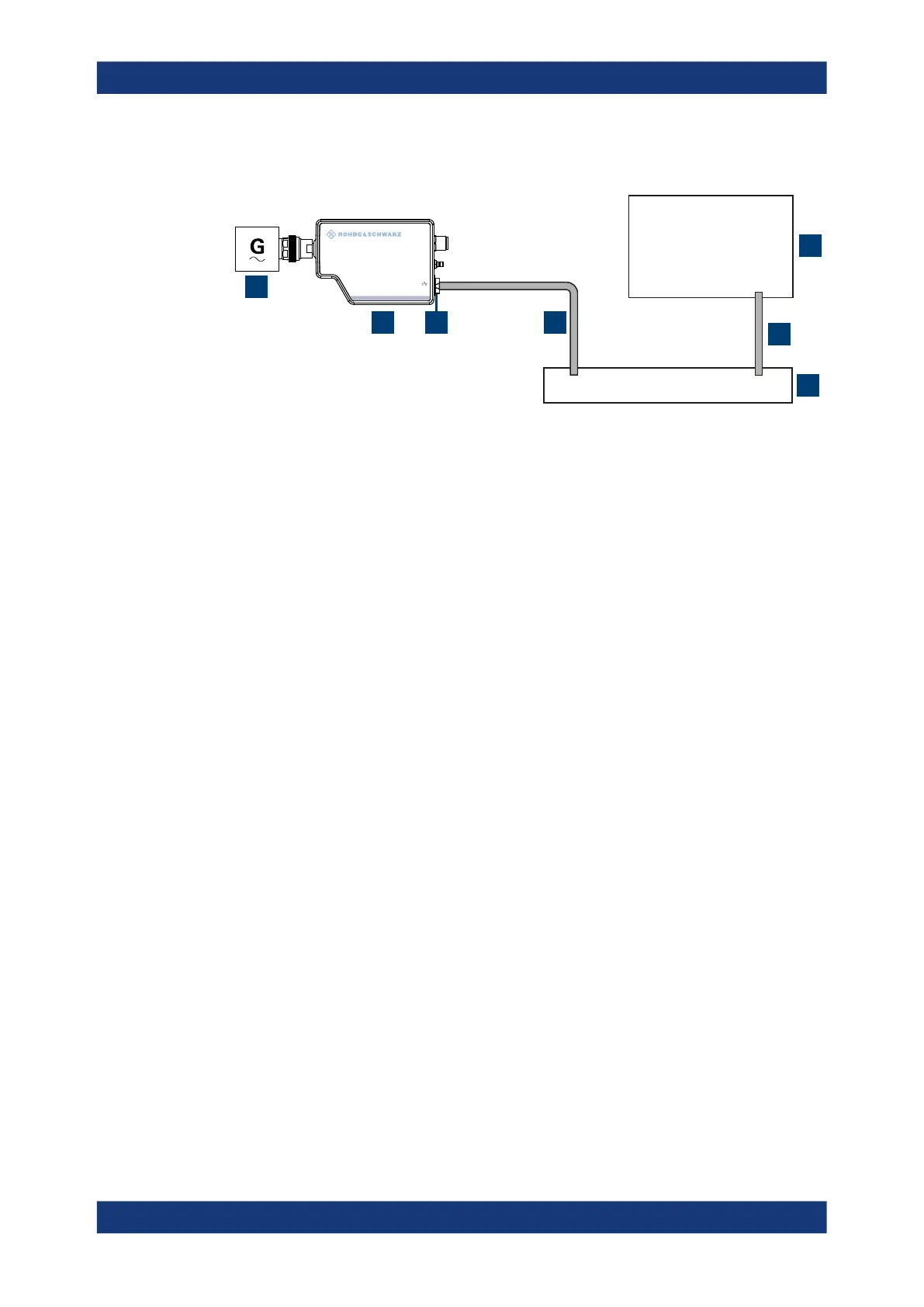
Figure 5-1: Setup with the web user interface
1 = Signal source
2 = LAN power sensor
3 = RJ-45 Ethernet connector
4, 6 = RJ-45 Ethernet cable
5 = Computer with a supported web browser installed
7 = Ethernet switch supporting PoE power delivery
1.
NOTICE! Incorrectly connecting or disconnecting the power sensor can damage
the power sensor or lead to erroneous results. Ensure that you connect or discon-
nect the power sensor as described in Chapter 3.4, "Connecting to a DUT",
on page 15.
Connect the power sensor to the signal source.
2. Connect the cables as shown in Figure 5-1.
For a detailed description, refer to Chapter 3.7.3, "Using a LAN connection",
on page 21.
Starting a measurement
1. Open a supported web browser.
2. Enter the instrument name or the IP address of the sensor you want to connect to.
Example: http://nrp33sn-123456
For details on how to find out the IP address or hostname, refer to Chapter 3.7.3.4,
"Assigning the IP address", on page 26 and Chapter 3.7.3.3, "Using hostnames",
on page 24.
Browser-based user interface

 Loading...

