Operating concepts
R&S
®
NRPxxS(N)
40User Manual 1177.5079.02 ─ 15
Setup
NRP
3-Path Diode Power Sensor
MHz to GHz, 100 pW to 200 mW (−70 dBm to +23 dBm)
SMART SENSOR TECHNOLOGY
1
2
3
4
6
5
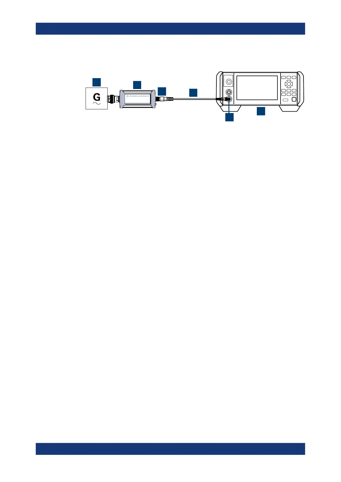
Figure 5-4: Setup with an R&S
NRX base unit
1 = Signal source
2 = R&S NRPxxS(N) power sensor
3 = Host interface connector
4 = R&S NRP‑ZK8 cable
5 = Sensor input connector of the R&S NRX
6 = R&S NRX base unit
1.
NOTICE! Incorrectly connecting or disconnecting the power sensor can damage
the power sensor or lead to erroneous results. Ensure that you connect or discon-
nect the power sensor as described in Chapter 3.4, "Connecting to a DUT",
on page 15.
Connect the power sensor to the signal source.
2. Connect the cables as shown in Figure 5-4.
If the power sensor is a R&S NRP LAN power sensor, you can set up a LAN con-
nection instead of using the sensor input connector of the R&S NRX. See Chap-
ter 3.7.3, "Using a LAN connection", on page 21.
Starting a measurement
For a detailed description of how to measure in this setup, refer to the user manual of
the R&S NRX.
1. Preset the R&S NRX and the connected R&S power sensors.
a) Press the [Preset] key.
b) Tap "Preset".
All parameters are set to their defaults.
2. Note: Turn off all measurement signals before zeroing. An active measurement
signal during zeroing causes an error.
a) Switch off the power of the signal source.
b) Press the [Zero] key of the R&S NRX.
c) Tap "Zero All Sensors".
3. Configure the measurement.
a) In the "Measurement Settings" dialog, select the "Measurement Type", for
example "Continuous Average".
b) Tap "Quick Setup" > "Auto Set".
R&S
NRX

 Loading...

