Chapter 8: Installation 8-5
Selecting the Display
Unit Location
8.3 Selecting the Display Unit Location
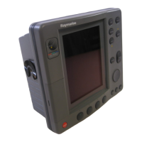
The displayunit can be mounted using the mounting bracket supplied, or
console mounted using the optionalflush-mounting kit.
The dimensions of the displayunits, including the bracket,is shown in
Figure 8-3 .
Whenplanningthedisplayinstallation,the followingshouldbeconsideredto
ensurereliableand troublefree operation:
• Convenience:Powertheunitandselectasuitablemountinglocationprior
to installing the display.
The mountinglocationshould be easilyaccessible to allow operationof
the front panel controls.
• Access:There must be sufficient spacebehind the displayto allowcable
connectionsto the rear panel connectors,avoidingtight bends in the cable.
• Interference:The selectedlocation should be far enough away from
devices that may cause interference,such as motors, generators and radio
transmitter/receivers (seethe EMC guidelines earlier in this section).
• Magneticcompass:Mount the display unit at least 3 ft (1m) away from a
magnetic compass.
• Cableruns:ThedisplayunitmustbelocatednearaDCpowersource.The
power cable supplied is 4.9ft. (1.5m),but a longer cable can be used if
required:referto Section 8.4.
The maximum length of cable between a master displayand the scanner
unit should not normally exceed 60 ft. (20 m). If you need to use a longer
cable,refer to the Pathfinder Radar Scanner Owner’s Handbook.
• Environment:Do not restrict airflowat the rearof the display unit;
the display incorporatesCold Cathode FlorescentLamps (CCFL),
which have a reduced lightoutput when the unit is very hot.
Ensurethereis adequateventilation,particularlyif thedisplayunit is
pod-mounted.
The display should be protected from physicaldamage andexcessive
vibration. Although the display unit is waterproof, it is good practice to
mount it in a protected area away from prolonged and direct exposure to
rainand salt spray.
81186_3.book Page 5 Thursday, August 22, 2002 8:23 AM

 Loading...


