8-10 hsb
2
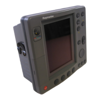
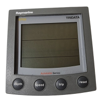
PLUS Series LCD Display
Mounting the Display
Unit
CAUTION:
Makesurethere are no hidden electricalwiresor other items behind the
locationbefore proceeding.Make surethereis sufficientrearaccess for
mountingand cabling.
1. Check the selectedlocation forthe unit. A clear, flat areaat least 9 in
(230 mm) wide by 8¼ in (210 mm) high, with at least 6 in (152 mm) of
clearancebehind the panel, is required.
2. Unpack theflush-mounting kit.
3. Using thesupplied template,trace out the display unit opening.
4. Drill a ½ in (12.7 mm) pilot hole in each corner of the cut-out area.
5. Using a suitablesaw, cut along the inside edge of the cut-out line.
6. Remove the mounting bracketknobs and bracket from the display unit.
Make sure that the unit fitsin the cut-outarea.
If the optional screw fitting is required,drill four 3/16 in (5 mm) holes as
indicated on the template.
Screw the studs into the holes provided at the rear of the display.
7. Connect the DC power cable, inter-unitcable, and any other accessory
cablesto the display. Avoid tight bends in the cables.
8. Place the gasket on the unit and slide the unit into the panel cut-out.
9. Use the flush-mounting kit to secure the unit to the console.
Alternatively, place a spacer over each of the four studs and secure with
the thumb nuts.
81186_3.book Page 10 Thursday, August 22, 2002 8:23 AM

 Loading...


