Section 7. Component Procedures Model 8210/8250 Maintenance Manual
Control Arm Assembly Steering and Controls
7-24 Publication: 1146945/001, Revised: 25 Sep 2018
Control Arm Removal
Park the truck on a level surface and
make sure all wheels are blocked to
prevent accidental movement.
N
OTE: Callouts in this procedure refer to the
illustration on page 7-23.
1. Release pressure in the hydraulic system
by pressing the lowering button on control
head.
2. If equipped with the optional keypad,
press the red OFF ( O ) key. Place the Main
ON/OFF Switch in the OFF position.
Disconnect the battery connector from the
truck.
3. Remove the lower and grille covers.
4. Remove the screws [14] securing the
control handle bumper stop [16].
5. Remove the control handle bumper stop
[16] and lay to one side.
6. Disconnect the wiring harness connector.
7. Remove the screw [12] and P-Clamp [10].
8. Remove the set screw [6] and remove the
pin [3].
9. Carefully remove the control arm handle
stem [4].
Control Arm Installation
NOTE: Callouts in this procedure refer to the
illustration on page 7-23.
1. Position the control arm handle stem [4]
on the stem mount [2].
2. Slide pin [3] through the stem mount [2],
and the handle stem [4] assembly. Make
sure to align the hole in the pin with the
hole in the stem mount [2].
3. Install the set screw [8] into the hole in pin
[3]. Tighten the set screw, then tap the end
of the pin to make sure it is seated
correctly.
4. Route the handle cable between the spring
sleeve flange [9] and the plastic washer
[11]. Reconnect the handle harness
connector.
5. Install screw [12] and the P-Clamp [10] to
secure the handle harness. Torque screw
to 11 ft. lbs. (15 Nm).
6. Adjust the angle arm proximity switch
(see page 7-81).
7. Install cable tie [13] to secure angle arm
proximity switch cable to handle harness.
8. Install the control handle bumper stop
[16]. Secure with screws [14].
9. Install the lower and grille covers.
10. Remove the blocks securing the truck.
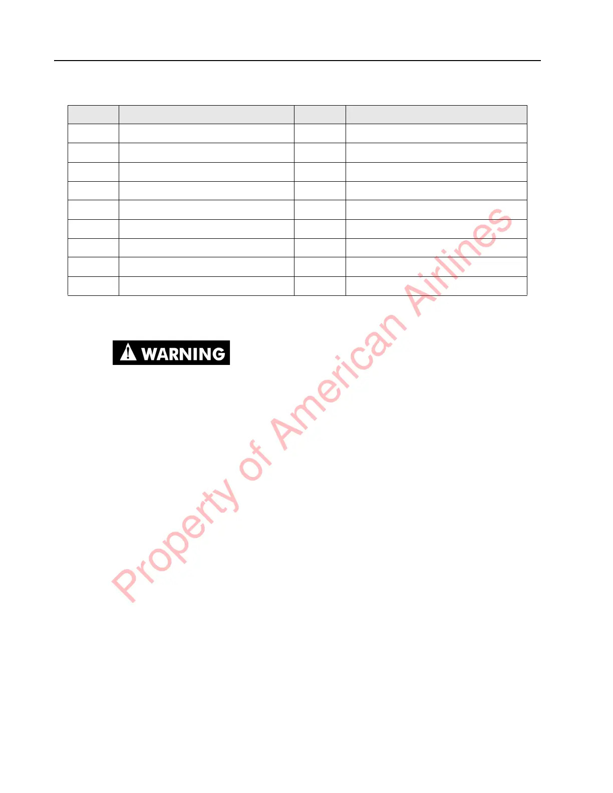
Item Description Item Description
1 Arm Angle Proximity Switch Assembly 10 P-Clamp
2 Stem Mount 11 Plastic Washer
3 Handle Pivot Pin 12 Screw, Button Socket Head
4 Handle Stem 13 Cable Tie
5 Bearing Race 14 Bolt, Shoulder
6 Set Screw 16 Bumper Stop
7 Torsion Spring 17 Grommet
8 Bearing 18 Screw
9 Spring Sleeve 19 Screw
Property of American Airlines
 Loading...