Model 8210/8250 Maintenance Manual Section 7. Component Procedures
Electrical Components Lift Motor
Publication: 1146945/001, Revised: 25 Sep 2018 7-91
Lift Motor
Lift Motor Removal
1. If equipped with the optional keypad,
press the red OFF ( O ) key. Place the Main
ON/OFF Switch in the OFF position.
Disconnect the battery connector from the
truck.
2. Remove the tractor covers.
3. Remove the hydraulic unit from the truck.
See “Hydraulic Unit Removal” on
page 7-98.
4. Remove the two bolts from the end cover
that attach the motor to the adapter body.
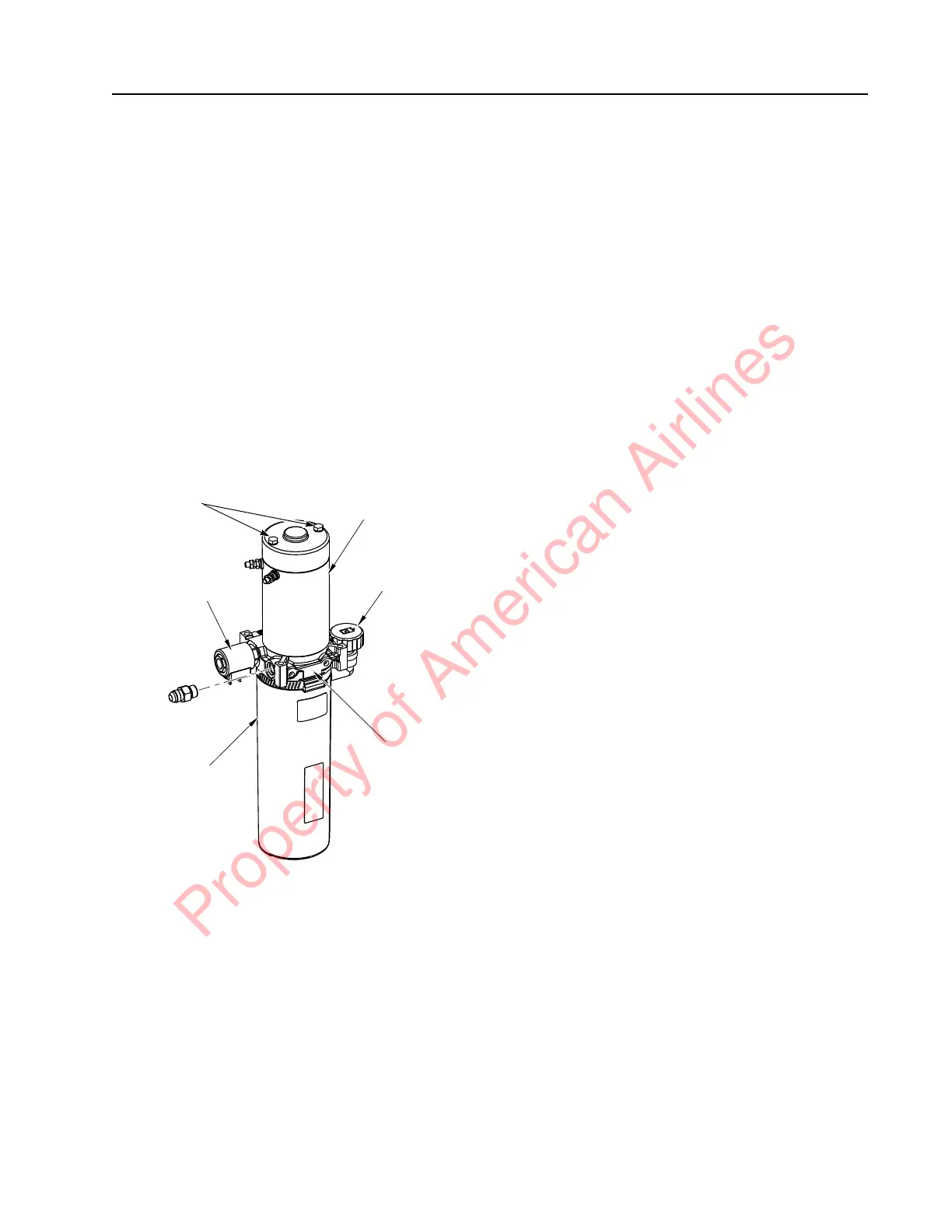
Figure 7-106. Motor End Cover Bolts
5. Separate the motor and the adapter body.
Lift Motor Installation
1. Stand the pump assembly on end, with
the adapter body facing up.
2. Set aside the pump drive coupling for later
reuse.
N
OTE: The coupling is the mechanical
connection between the pump shaft and
the electric motor armature shaft. It
may have been removed with the motor.
3. Insert the pump drive coupling on the end
of the pump shaft. Fill the coupling cavity
with anti-seize compound (P/N 990-638).
4. Rotate the pump or the motor shaft to
align the motor shaft correctly with the
coupling.
5. Install the new motor on the adapter body.
Rotate the pump or the motor shaft if
necessary to allow the motor to contact the
adapter body.
6. Insert the screws into the motor end plate,
through the motor and into the adapter
body.
7. Make sure the motor is mating flush with
the adapter body. Torque screws to 40 to
45 in. lb. (4.5 to 5.1 Nm) maximum.
8. Install the hydraulic unit. See “Hydraulic
Unit” on page 7-97.
Lift Motor Brush Replacement
1. Remove the lift motor from the hydraulic
assembly before inspecting the brushes.
2. Remove the two bolts from the motor end
cover. Remove the end cover to access the
brushes. See Figure 7-106.
3. Push each brush back into the holder to
disengage the springs. Remove the nuts
and washers from the side of the drive end
head. Remove the brush assembly, then
remove each brush and replace with a new
one.
Lift Motor
Fill/Vent Plug
Adapter Body
Reservoir
Solenoid
End Cover
Bolts
Property of American Airlines