Section 7. Component Procedures Model 8210/8250 Maintenance Manual
Drive Unit Assembly Drive and Brake
7-28 Publication: 1146945/001, Revised: 25 Sep 2018
Drive Unit Assembly
The drive unit assembly includes the traction
motor, electromagnetic brake assembly, drive
wheel, and drive unit (transmission).
N
OTE: For replacement parts information refer
to the Parts Manual.
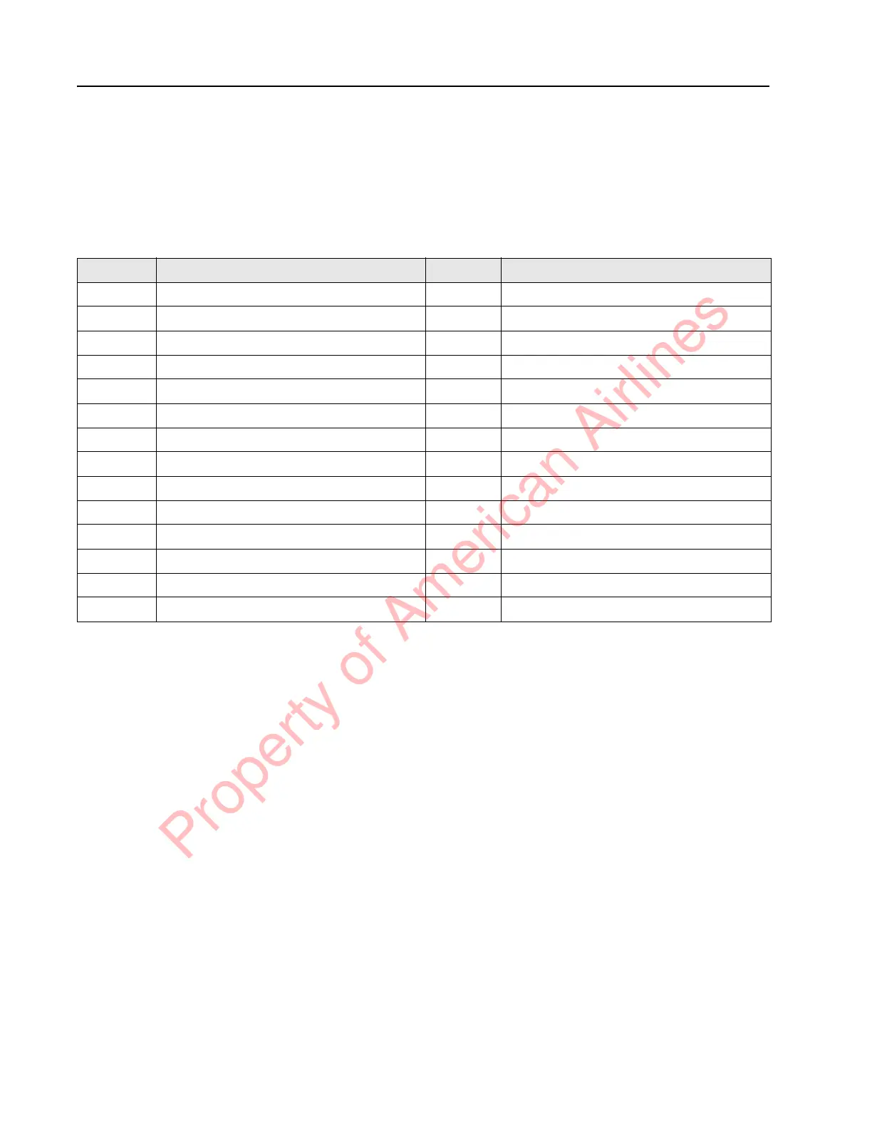
Table 7-1. Legend for “Drive Unit, Exploded View” on page 7-29
Item No. Description Item No. Description
1 Housing, Gear Case 17 Drive Axle
2 Cover, Gear Case 18 Bearing, Sealed
3 Cap Screw, Socket Head 19 Spacer, Bearing
4 Pinion, Drive 1
st
Stage 20 Stud, Wheel
5 Gear Set, 2
nd
Stage 21 Cap Screw, Socket Head
7 Gear Set, Output 22 Cap Screw, Socket Head
9 Bearing, Steering 23 Washer, Lock
10 Plug, Fill/Level 25 Axle, 2
nd
Stage
11 Plug, Drain 26 Sleeve (roll pin)
12 Bearing, Sealed 27 Ring, Retaining
13 Bearing Set, Cup and Cone 28 Vent
14 Seal, Ring 29 Motor, Traction
15 Screw, Hex Head 30 Brake (with Boot)
16 Seal, Shaft 31 Brake Hub Mounting Location
Property of American Airlines
 Loading...