Section 7. Component Procedures Model 8210/8250 Maintenance Manual
Drive Unit Drive and Brake
7-30 Publication: 1146945/001, Revised: 25 Sep 2018
Drive Unit
Drive Unit Removal
1. Lower the forks. If equipped with the
optional keypad, press the red OFF ( O )
key. Place the Main ON/OFF Switch in the
OFF position. Disconnect the battery
connector.
2. Remove the lower and grille covers
(page 7-8).
3. Remove the bumper. See “Bumper
Removal” on page 7-13.
Use extreme care whenever the truck is
jacked up. Keep hands and feet clear
from the vehicle while jacking the truck.
After the truck is jacked, put solid blocks
beneath it to support it. DO NOT rely on
the jack alone to support the truck. For
details, see “Jacking Safety” on
page 2-10.
4. Jack the truck and block the frame.
5. Remove the drive wheel. See “Drive Wheel”
on page 7-34.
6. Remove the screws [2] that secure the
control arm stop [3]. See Figure 7-39.
Figure 7-39. Control Handle Assembly Removal
7. Disconnect the handle harness and arm
angle proximity switch.
Figure 7-40. Angle Arm Proximity Switch Disconnected
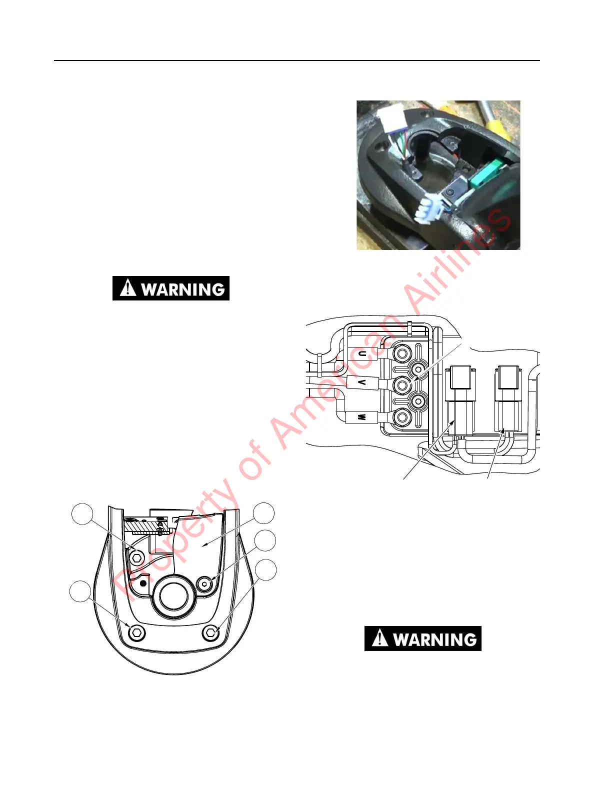
8. Disconnect the cables/wire from the
traction motor to the terminal block on the
drive unit housing. See Figure 7-41.
Figure 7-41. Terminal Block
9. Disconnect the brake connector and the
speed and temperature sensor connector
on the drive unit housing.
10. Feed the control wiring harness and power
cables through the drive unit pivot mount.
11. Remove the screws [1] that secure the
control handle assembly to the drive unit
assembly. See Figure 7-39.
The drive unit assembly may fall free
from its mounting after the bolts are
removed.
Terminal
Block
Connections
Brake
Connector
Speed and Temp
Sensor Connector
Property of American Airlines