Section 7. Component Procedures Model 8210/8250 Maintenance Manual
Traction Amplifier Electrical Components
7-74 Publication: 1146945/001, Revised: 25 Sep 2018
Traction Amplifier
NOTE: For replacement parts information refer
to the Parts Manual.
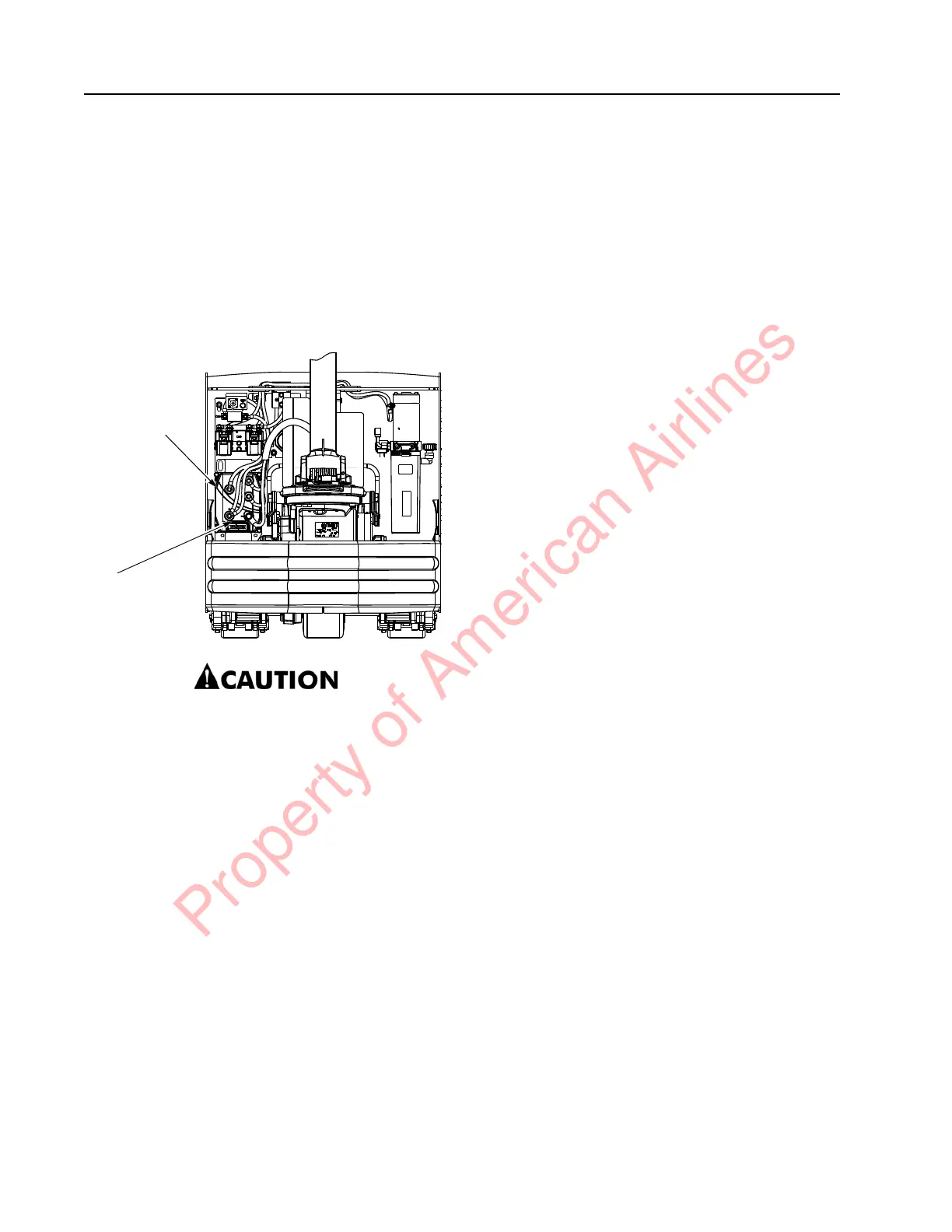
The traction amplifier is installed in the left side
electrical compartment of the tractor. See
Figure 7-90.
Figure 7-90. Traction Amplifier Location
6349-009.jpg
Do not open the traction amplifier.
Opening the traction amplifier could
cause damage to it and voids the
warranty.
To Clean the Traction Amplifier
1. If equipped with the optional keypad,
press the red OFF ( O ) key. Place the Main
ON/OFF Switch in the OFF position.
Disconnect the battery connector from the
truck.
2. Remove the tractor covers.
3. Discharge the capacitors in the traction
amplifier by connecting a load (such as a
contactor coil) across the amplifier’s TA B+
and TA B– terminals.
4. Clean the traction amplifier with a moist
rag. Let it dry before connecting the
battery.
5. Make sure the power cable connections
are tight. Do not stress the cable
connections or put strain on internal
components.
Traction Amplifier Removal
1. If equipped with the optional keypad,
press the red OFF ( O ) key. Place the Main
ON/OFF Switch in the OFF position.
Disconnect the battery connector from the
truck.
2. Remove the tractor covers.
3. Discharge the capacitors in the traction
amplifier by connecting a load (such as a
contactor coil or a horn) across the
amplifier’s TA B+ and TA B– terminals.
4. Push the locking tab and disconnect the
J1 connector from the traction amplifier.
See Figure 7-90.
5. Disconnect the power cables (terminals TA
B+ and TA B–) on the traction amplifier. Do
not stress the power cable connections.
Disconnect the traction motor cables
(terminals U, V, and W) at the traction
amplifier.
6. Remove the hex flange head screws
securing the traction amplifier to the
electrical panel. Remove the traction
amplifier.
Traction Amplifier Installation
NOTE: All traction amplifiers are preset to
factory default specifications.
1. Secure the traction amplifier to the
electrical panel with the previously
removed hex flange head screws. Torque
screws to 11 ft. lbs. (14.9 Nm).
2. Connect the power cables (terminals TA
B+ and TA B–) on the traction amplifier.
Torque screws to 80 to 100 in. lb. (9.1 to
11.3 Nm) maximum. Do not stress the
cable connections and put strain on
internal components.
3. Connect the J1 connector and traction
motor connectors (terminals U, V, and W)
to the traction amplifier.
4. Connect the battery connector.
Traction
Amplifier
J1
Connector
Property of American Airlines