Section 7. Component Procedures Model 8210/8250 Maintenance Manual
Drive Unit Drive and Brake
7-32 Publication: 1146945/001, Revised: 25 Sep 2018
3. Place the case in a fabricated assembly
base and carefully press the drive axle [17]
in the gear case [1].
4. Position the drive unit on the work bench
with the gear case side up. Install the
output gear [7] in the case and secure with
the retaining ring [27].
5. Install the 2
nd
stage gear set [5].
6. Install the traction motor bearing [10,
Figure 7-102 on page 7-86], retaining ring
[9], and seal [8] in the gear case if removed
previously.
N
OTE: The seal must be installed correctly with
its open side and seal ring positioned
towards the bearing.
7. Carefully slide the traction motor
armature shaft into the gear case if
removed previously. See “Traction Motor”
on page 7-86.
Make sure that the motor end cap is
installed before proceeding to the next
step.
8. Install the pinion gear [4] and the pinion
nut [20] on the armature shaft. Torque the
pinion nut to 25.8 ft. lb. (35 Nm).
9. Install the shaft seal [16], speed sensor
pinion gear [17], washer [18], and hex
screw [19] to the end of the armature.
Refer to Figure 7-102 on page 7-86,
10. Use gasket compound on the mating
surface and install the gear case cover [2].
11. Torque the nine cover bolts [3] to
16.9 ft. lb. (23 Nm).
12. Install the two screws [40] to secure the
speed sensor cover assembly [21] to the
gear case cover. Torque the screws to 23.8
in. lb. (2.7 Nm).
N
OTE: Make sure the speed sensor cable is
correctly seated in the grommet to
prevent damage from contact with the
linkage when the drive unit turns.
Drive Unit Installation
Make sure the main ON/OFF switch is
OFF and the battery connector is
disconnected before you start.
1. Install the steer bearing assembly using
ten Allen head bolts, if it was removed
previously. Torque bolts to 48.6 ft. lb.
(66 Nm).
2. Install the drive unit assembly to the pivot
frame. Feed the harness and cables
through the drive unit housing to the
locations where they were previously
removed.
3. Secure the assembly with the ten Allen
head bolts removed previously. Torque
bolts to 336 to 384 in. lb. (38.0 to 43.4
Nm).
4. Feed the wire harness and power cables
through the pivot tube.
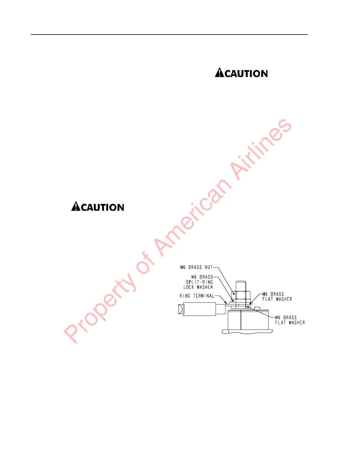
5. Reconnect the cables/wire to the terminal
block on the drive unit. See Figure 7-43 for
correct hardware order. Torque the brass
nuts to 26.5 in. lb. (3 Nm) to secure the
phase cables.
Figure 7-43. Hardware Stack for Phase Cables
6. Reconnect the brake connector and the
speed and temperature sensor connector
on the drive unit housing.
7. Install the drive wheel. See “Drive Wheel”
on page 7-34.
8. Unblock the truck.
9. Make sure the drive unit is filled to the
correct level with gear oil. See “Lubrication
Equivalency Chart” on page A-2. The drive
Property of American Airlines