Section 7. Component Procedures Model 8210/8250 Maintenance Manual
Drive Wheel Drive and Brake
7-34 Publication: 1146945/001, Revised: 25 Sep 2018
Drive Wheel
NOTE: For replacement parts information refer
to the Parts Manual.
Drive Wheel Removal
1. Park the truck on a level surface.
2. If equipped with the optional keypad,
press the red OFF ( O ) key. Place the Main
ON/OFF Switch in the OFF position.
Disconnect the battery connector from the
truck.
Use extreme care whenever the truck is
jacked up. Keep hands and feet clear
from the vehicle while jacking the truck.
After the truck is jacked, put solid blocks
beneath it to support it. DO NOT rely on
the jack alone to support the truck. For
details, see “Jacking Safety” on
page 2-10.
3. Remove the bumper. See “Bumper
Removal” on page 7-13.
4. Jack and block the truck under the tractor
frame. See “Jacking Safety” on page 2-10.
5. Remove the five drive wheel mounting
nuts. See Figure 7-45.
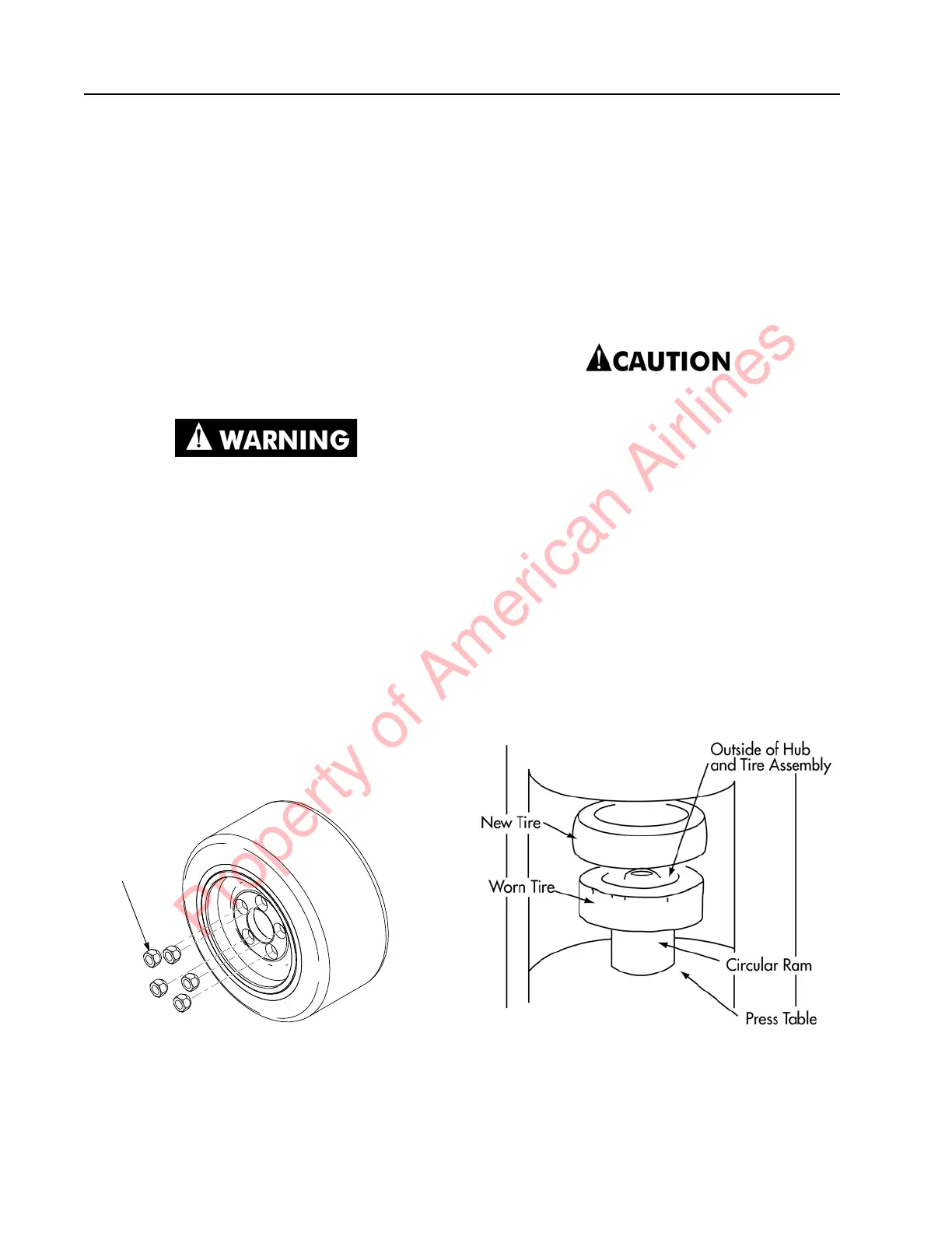
Figure 7-45. Drive Wheel Nuts
6. Remove the drive wheel.
Tire Replacement
Any misalignment of the tire and hub while the
tire is being pressed on the hub can cause
damage to the hub. For this reason, chamfers
are provided on the outside edge of the hub and
on the end of the inside diameter of the tire’s
metal insert. The chamfers help to center the
hub and tire during pressing and to reduce the
possibility of misalignment.
To prevent damage, the hub must be
installed on the circular ram with the
chamfered side up.
1. Check the inside surface of the metal
insert on the new tire. Remove any scaling
or rust with sandpaper. Clean the inside of
the metal insert.
2. Place a circular ram on the press table.
The length of the ram must be longer than
the width of the old tire to permit complete
removal of the old tire. The outside
diameter of the ram must be small enough
to fit loosely in the insert of the tire but
must be large enough to rest squarely on
the flat surface on the outer edge of the
hub. See Figure 7-46.
Figure 7-46. Tire Replacement
3. If the outside edge of the hub is not flush
with the edge of the metal insert in the old
tire, measure how far the hub is recessed
inside the tire. The new tire must be
Property of American Airlines
 Loading...