Model 8210/8250 Maintenance Manual Section 3. Systems Overview
Service Display
Publication:1146945/001, Revised: 25 Sep 2018 3-17
Service Display
• Connect the service key (see “Special
Tools” on page 3-21) in connection point
J5, place the Main ON/OFF Switch in the
ON position. If equipped with the optional
keypad, enter your PIN-key code and then
press the green ON ( | ) key to start the lift
truck.
• The battery status is displayed in the
alpha-numerical field (A) and the battery
indicator symbol (D) is illuminated.
• Press horn button (S18) to toggle between
Service Display modes. See Table 3-1.
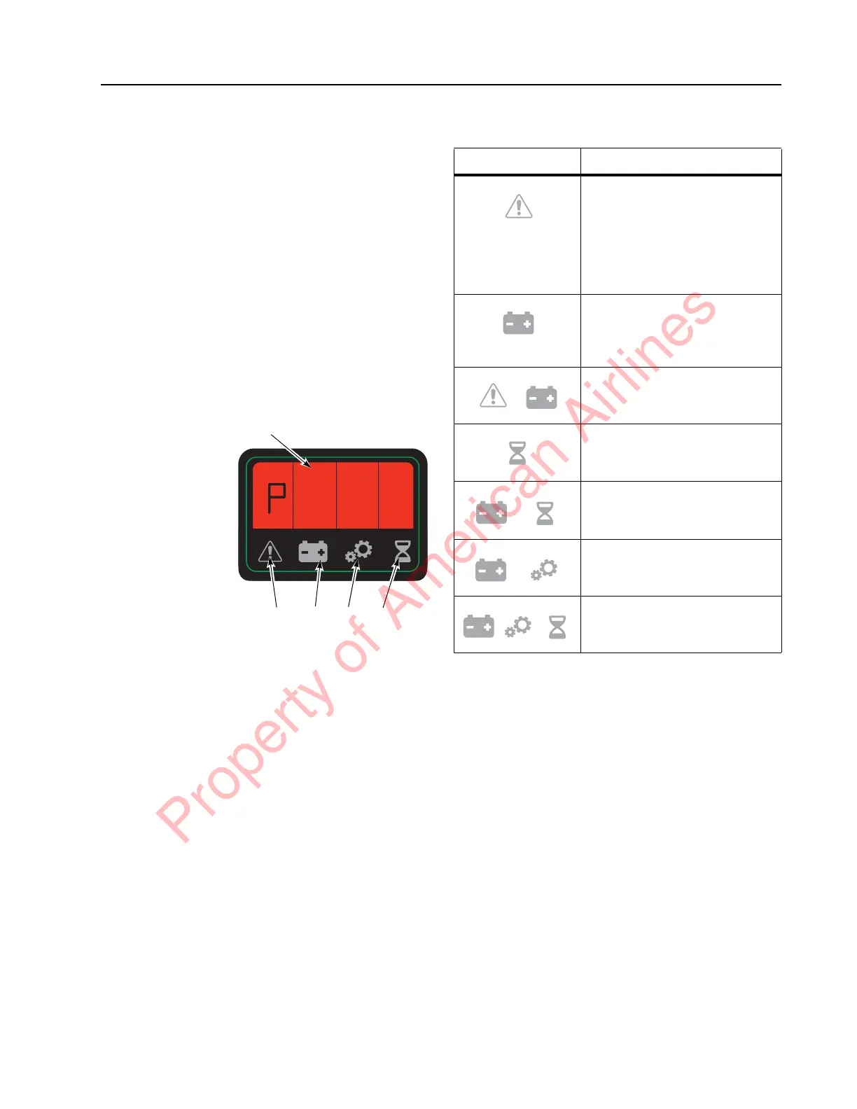
Figure 3-7. Operator Display
P0010517.png
Table 3-1. Service Display Modes
* Digital inputs/outputs are displayed by
highlighting the figure segments of four of the
alpha-numerical field figures (A) in the operator
display. See
“Digital Inputs/Outputs from
Traction Amplifier and VM”
.
Digital Inputs/Outputs from
Traction Amplifier and VM
Select service display mode “C” detailed in the
section “Service Display” on page 3-17. Also see
Table 3-1, “Service Display Modes,” on
page 3-17.
The digital input/output functions are
displayed by illuminating the figure segments of
four of the numerical field figures in the
operator display.
A
C
E
D B
Explanation of
Symbols:
A = Alpha-Numeric
Field
B = Hour Meter
Indicator
C = Parameter
Indicator
D = Battery
Indicator
E = Error Indicator
Flashing Symbol Displayed Data
Throttle Request (Speed
reference value) sent to
traction amplifier (TA).
-127 represents full throttle
with forks-leading
+127 represents full throttle
with forks-trailing
Digital inputs/outputs from
traction amplifier (TA) and
vehicle manager (VM).
* See explanation following
Battery voltage (V) at vehicle
manager (VM)
Traction Motor RPM
(increases as travel is
requested)
Phase Current RMS
TA Temp. °C
Motor Temp. °C
Property of American Airlines