Model 8210/8250 Maintenance Manual Section 7. Component Procedures
Electrical Components Lithium-Ion Battery
Publication: 1146945/001, Revised: 25 Sep 2018 7-53
4. Remove any cables/plugs/debris from the
area before installing.
5. Install the Cell Module Assembly Drip
Protector, if installing the second Cell
Module Assembly in the high capacity
lithium-ion battery. (This is the Cell
Module Assembly located below the
charger).
6. Install the four Cell Module Assembly
mounting bolts. Torque the bolts to
9.9 ft. lb. (13.4 Nm).
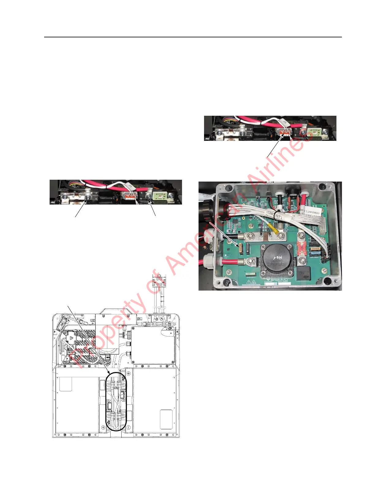
7. Install the B+ and B- terminals onto the
Cell Module Assembly. Torque fasteners to
6.6 ft. lb. (9 Nm).
Figure 7-68. CMA Connections
8. Install the Cell Module Assembly
Interconnecting Cables, if installing a
second Cell Module Assembly in the high
capacity lithium-ion battery.
Figure 7-69. CMA Innerconnect Cable Location
9. Install the Cell Module Assembly terminal
covers. Torque fasteners to 6.7 ft. lb.
(10.9 Nm).
10. Plug in the Battery Monitoring Unit
communication connector into the Battery
Monitoring Unit.
Figure 7-70. BMU Communication Connector Location
11. Install the BMC F1 Fuse.
Figure 7-71. BMC FI Fuse Location
NOTE: The lithium-ion battery might wake up.
12. Install the BMC cover by screwing in the
four BMC cover screws. Torque fasteners
to 1.3 ft. lb. (1.8 Nm).
13. Install the front cover. See “Front Cover
Installation” on page 7-50.
14. Install the top cover. See “Top Cover
Installation” on page 7-49.
15. For a high capacity lithium-ion battery,
repeat steps 1 through 10).
16. Reconnect the battery connector. Place the
Main ON/OFF Switch in the ON position.
If equipped with the optional keypad, enter
your PIN-key code and then press the
green ON ( | ) key.
17. Test the operation of the truck.
CMA B+
Terminal
CMA B–
Terminal
Property of American Airlines