● 5: Frequency level detection signal (FDT1)
See related parameters E1.04...E1.05.
● 6: Frequency level detection signal (FDT2)
See related parameters E1.06...E1.07.
● 7: Logic control phase completed
Pulse output indicating signal when each phase is complete in logic con‐
trol.
● 8: Under voltage stop
Output indicating signal when the frequency converter is at under volt‐
age.
● 9: Frequency converter over load pre-warning 1
Output indicating signal after the output current exceeds the set value of
parameter E1.08 for the time set by E5.13.
● 10: Motor over load pre-warning
Output indicating signal when the output current exceeds the set value
of parameter E1.09 ‘Motor over load pre-warning level setting’.
● 11: Over torque
Output indicating signal when the motor torque exceeds the torque limit
settings in vector control.
● 12: Frequency converter in fault
Output indicating signal when the frequency converter is in fault.
● 13: Fault auto reset signal output
Output indicating signal when the frequency converter tries to auto re‐
set.
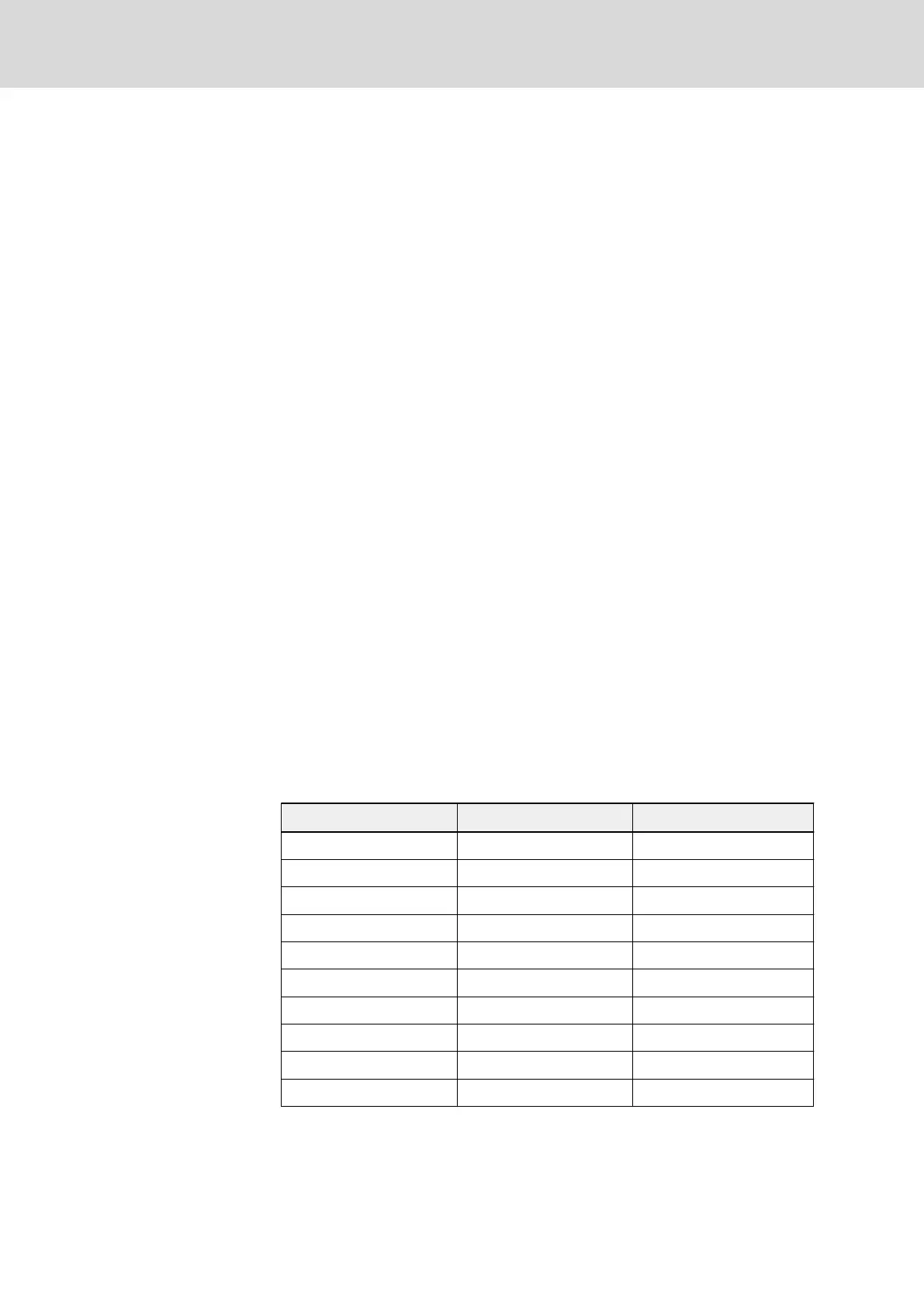
● 14: Frequency converter over load pre-warning 2
Output indicating signal when load of K1 times rated current is applied
to the frequency converter for T1 seconds and warning message O.L.-3
occurs on panel at the same time. Fault code O.L.-1 occurs if the same
load keeps for another T2 seconds. The relationship of T1, T2 and K1
are shown below:
Load K1 (%) T1/s T2/s
110...115 3600 360
116...120 1800 180
121...130 600 60
131...140 300 30
141...150 60 6
151...160 30 3
161...170 20 2
171...180 10 1
181...190 5 0.5
191...200 1 0.1
Tab. 7-14: K1, T1 and T2 relationship
Bosch Rexroth AG DOK-RCON02-FV*********-IB08-EN-P140/259
Rexroth Frequency Converter Fv
Parameter Settings