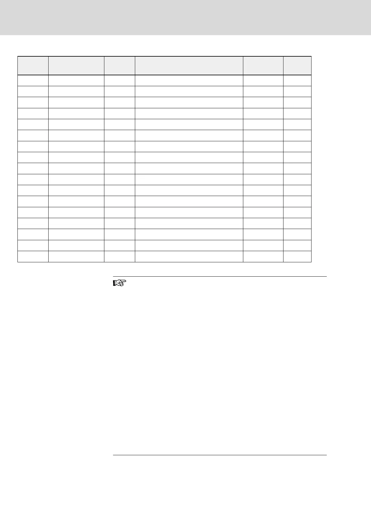
Model FELB Typecode
FELB
Quantity
FELR Typecode FELR Type
FELR
Quantity
0K40 Internal – 0240-N750R-D 750Ω/240W 1
0K75 Internal – 0500-N550R-D 550Ω/500W 1
1K50 Internal – 0800-N275R-D 275Ω/800W 1
2K20 Internal – 01K2-N180R-D 180Ω/1.2kW 1
4K00 Internal – 02K0-N110R-D 110Ω/2.0kW 1
5K50 Internal – 01K5-N150R-D 150Ω/1.5kW 2
7K50 Internal – 04K5-N055R-A 55Ω/4.5kW 1
11K0 Internal – 06K0-N040R-A 40Ω/6.0kW 1
15K0 Internal – 08K0-N027R-A 27Ω/8.0kW 1
18K5 FELB02.1N-45K0 1 10K0-N022R-A 22Ω/10.0kW 1
22K0 FELB02.1N-45K0 1 12K5-N018R-A 18Ω/12.5kW 1
30K0 FELB02.1N-30K0 2 10K0-N27R2-A 27.2Ω/10.0kW 2
37K0 FELB02.1N-45K0 2 10K0-N022R-A 22Ω/10.0kW 2
45K0 FELB02.1N-45K0 2 12K5-N018R-A 18Ω/12.5kW 2
55K0 FELB02.1N-30K0 3 12K5-N022R-A 22Ω/12.5kW 3
75K0 FELB02.1N-45K0 3 10K0-N022R-A 22Ω/10.0kW 6
90K0 FELB02.1N-45K0 3 10K0-N022R-A 22Ω/10.0kW 6
Tab. 10-11: Brake resistor selection_OT = 40 %
● In the table in the manual, the recommended resistance of
the brake resistor is 100 % braking torque, selected accord‐
ing to necessity. If the actually needed torque is not 100 %,
the resistance of the brake resistor in the table should be ad‐
justed in inverse proportion, i.e. how much the brake torque
increases based on 100 %, the resistance of the brake resis‐
tor should decrease by the same amount, vice versa.
● When selecting brake resistor R
b
, make sure the current I
c
which flows through the resistor is less than the current out‐
put ability of the brake chopper. The current I
c
through the
brake resistor can be calculated by formula I
c
= U
d
/R
b
, in
which U
d
is the braking operating voltage of brake chopper.
● After the adjustment of the resistance of brake resistor, the
power of brake resistor should be also adjusted appropriate‐
ly. The power can be calculated by formula P
max
= U
d
2
/ R
b
.
According to the actual working condition, the braking ratio
OT % can be selected to reduce the power of brake resistor
reasonably for intermittent braking load. The power of brake
resistor can be calculated by formula P
R
= K × P
max
× OT %,
in which K is the derating coefficient of brake resistor. The
selection of the brake torque should be in general smaller
than 150 % of the rated motor torque, or consulting the tech‐
nical support for more information.
Bosch Rexroth AG DOK-RCON02-FV*********-IB08-EN-P204/259
Rexroth Frequency Converter Fv
Accessories