10 February 2005 ELECTRICAL COMPONENTS
3-49
Replacement
Adjustment
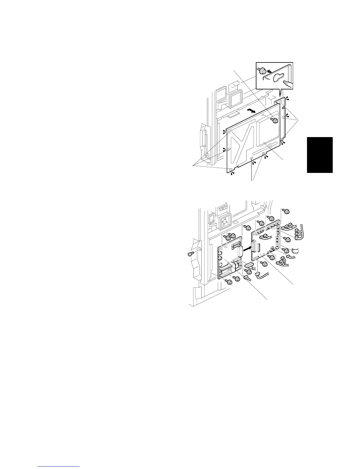
3.10.2 BICU BOARD AND CONTROLLER BOARD
1. Rear cover ( 3.4.2)
2. Remove the screw [A], and then loosen
the eight screws [B].
3. Slide the controller box cover [C] to the
right, and then remove it.
4. BICU board [B] ( x 14, x 7)
NOTE:
1) Compare the settings of the
dip switches on the old
board with the settings on
the new board. If they are
different, change the
settings on the new board
to make them identical.
2) When replacing the
controller board only; leave
the 14 connectors
connected, remove the
seven screws, and
disconnect the BICU board
from the controller board.
5. Controller board [C] ( x 7, x 2)
NOTE: Remove the NVRAM, DIMMs, and optional boards from the old
controller board and install them on the new one.
B156R924.WMF
B156R817.WMF
[A]
[B]
[C]
[B]
[B]
[C]
[B]



 To Next Page