5. OPERATION
IMR02L04-E3
5-2
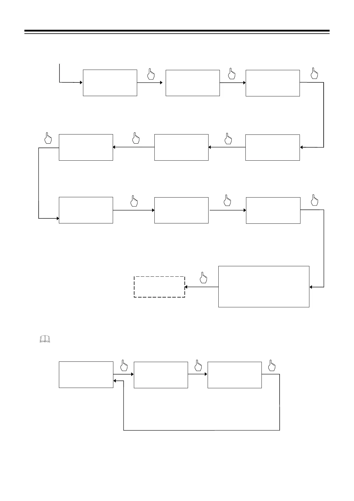
Check the set value of the Setting limiter at the Function block 71 (F71.).
F21.12: PV bias
F21.13: PV digital filter
F21.14: PV ratio
F21.15: PV low input cut-off
The parameters above may be set in the
Setup setting mode.
PV
K PGDP
M:S
SV
F21.03R 00000
Decimal point position
PV
K PGSH
$
M:S
SV
F21.04R 00400
Input scale high
PV
K PGSL
$
M:S
SV
F21.05R 00000
Input scale lo
PV
KPPOV
$
M:S
SV
F21.06R 00420
Input error determination
point (high)
PV
KPPUN
$
M:S
SV
F21.07 -0020
Input error determination
point (low)
PV
KPBOS
M:S
SV
F21.08- 00000
Burnout direction
PV
KPSQR
M:S
SV
F21.09- 00000
Square root extraction
PV
K PFRQ
M:S
SV
F21.10 0 00000
Power supply frequency
PV
KPSMP
M:S
SV
F21.11 - 00001
Sampling cycle
Check Decimal point position.
0000: No decimal place
Select Burnout direction.
00000: Upscale (Factory set value)
00001: Downscale
Check Input scale high.
00400: 400 C
Check Input scale low.
00000: 0 C
Continued from the
previous parameter
Check Input error determination
point (high).
00420: 420 C
Check Input error determination
point (low).
0020: 20 C
Return to
Function block 21
(F21.)
Select Square root extraction.
00000: Unused (Factory set value)
00001: Used
Select Power supply frequency.
00000: 50 Hz (Factory set value)
00001: 60 Hz
Select Sampling cycle.
00000: 50 ms
00001: 100 ms (Factory set value)
00002: 250 ms
PV
F71.
M:S
SV
FIX000SCALE
Function block 71
(F71.)
PV
S0SLH
$
M:S
SV
F71.01R 00400
Setting limite
high
PV
LBSLL
$
M:S
SV
F71.02R 00000
Setting limite
lo
Check Setting limiter high.
00400: 400 C
[Range: Setting limiter low to
Input range high]
Check Setting limiter low.
00000: 0 C
[Range: Input range low to
Setting limiter high]
(P. 4-43, P. 4-49)

 Loading...


