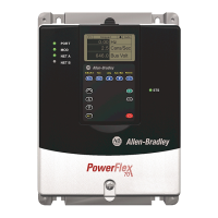
PowerFlex® 700L Liquid-Cooled Drive User Manual
Publication 20L-UM001D-EN-P
Index
Numerics
700 Active Converter (regenerative drive
only)
removing control cassette
Frame 2, 2-7
Frame 3A, 3-13
Frame 3B, 3-13
700 Vector Control (standard)
fault descriptions, 6-4
information reference, P-1
removing control cassette
Frame 2, 2-8
Frames 3A and 3B, 3-14
700L Active Converter (regenerative drive
only)
information reference, P-1
700L AlarmStatus parameter (700S Phase
II Control), 5-7
700L EventStatus parameter (700S Phase
II Control), 5-5
700L FaultStatus parameter (700S Phase II
Control), 5-6
700L service information reference, P-2
700S Phase II Control (optional)
alarm descriptions, 6-6
fault descriptions, 6-5
information reference, P-1
removing control cassette
Frame 2, 2-8
Frames 3A and 3B, 3-15
A
AC input
general grounding requirements, 1-2
ground
Frame 2, 2-11
Frames 3A and 3B, 3-22
power conditioning, 1-2
wiring
Frame 2, 2-12
Frames 3A and 3B, 3-23
AC supply
source considerations, 1-1
unbalanced, ungrounded or resistive
grounded systems, 1-2
Accel Mask parameter (700 Vector Control),
5-3
Accel Owner parameter (700 Vector
Control), 5-4
active converter (regenerative drive only)
information reference, P-1
removing control cassette
Frame 2, 2-7
Frame 3A, 3-13
Frame 3B, 3-13
agency certification, A-1
air flow clearance requirements
Frame 2, 2-2
Frames 3A and 3B, 3-2, 3-7
alarm
clearing, 6-6
descriptions, 6-6
Alarm 1 @ Fault parameter (700 Vector
Control), 5-2
Alarm Config 1 parameter (700 Vector
Control), 5-2
Alarms Parameter Group (700 Vector
Control), 5-2
altitude derating guidelines, A-4
ambient derating guidelines, A-4
armored cable, 1-6
B
biocide use in coolant, 4-8
bus capacitors - discharging, P-4
C
cables, power
armored, 1-6
insulation, 1-4
separation, 1-4
shielded, 1-5
unshielded, 1-5
capacitors - bus discharging, P-4
carrier frequency derating guidelines, A-4
catalog number explanation, P-5
CE conformity, 1-7
clearance for air flow
Frame 2, 2-2
Frames 3A and 3B, 3-2, 3-7
clearing
alarms, 6-6
faults, 6-3
Comm Control Parameter Group (700
Vector Control), 5-3

 Loading...


