PowerFlex® 700L Liquid-Cooled Drive User Manual
Publication 20L-UM001D-EN-P
Summary of Changes
The information below summarizes the changes to this manual since its last
release (July 2007):
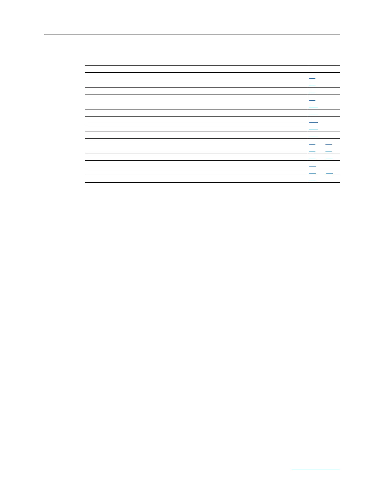
Description of New or Updated Information Page(s)
Revised conditions in the “Essential Requirements for CE Compliance” section. 1-8
Corrected overall height dimension in Figure 2.1 and Detail A dimension. 2-2
In the Equipment Lifting section, added subsection “Attaching the Lifting Feet to the Drive.” 2-4
Added Frame 2 information to remove PowerFlex 700S Phase II Control cassette. 2-8
Added Frame 2 “Selecting/Verifying Control Transformer Voltage” section. 2-12
In Figure 2.14, added Frame 2 TB1 details when TB4 is not present. 2-19
Added Frame 2 control synchronization information for 700S Phase II Control. 2-21
Added new information for Frame 3A and 3B to install the vented top cover. 3-16
Added “Selecting/Verifying Control Transformer Voltage” section for Frame 3A & 3B. 3-23
Updated Table 4.A and Table 4.G. 4-5 and 4-8
Added action to take for Table 6.B and 6.C. 6-4 and 6-5
Added PowerFlex 700S Phase II Control information to specifications. A-2 and A-3
Added Derating Guidelines. A-4
Added Tables A.H, A.I, A.J, and H.K for Frame 3A and 3B common bus inverter power module DC input fusing. A-7 and A-8
Added new schematic for Frame 2 drive without TB4 connections. B-4
 Loading...


