P3 - Pakscan Master Station Technical Manual
12 of 136 Publication PUB059-002-00 Issue 06/15
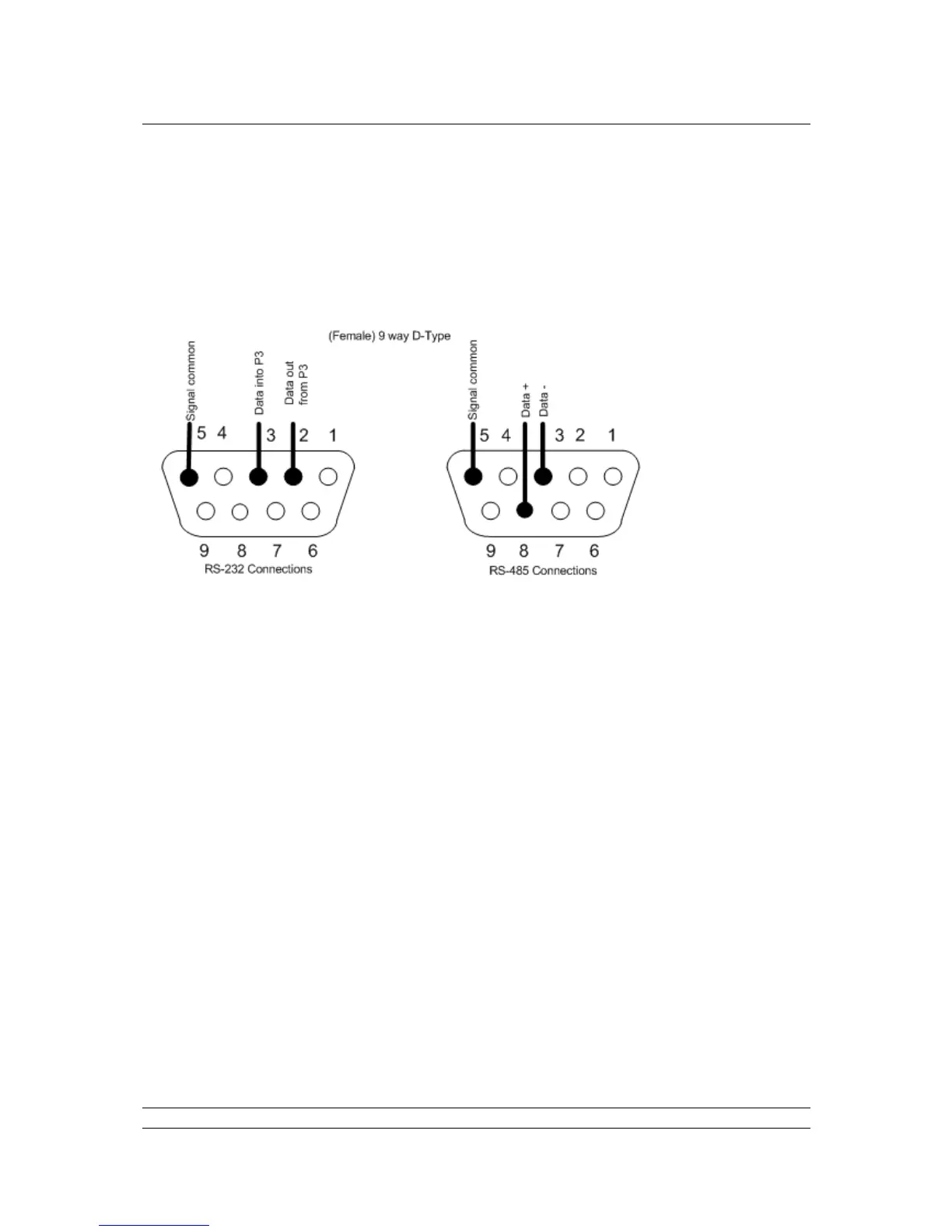
1.2 Host Serial Communications Connections
The serial data connections are via the D-type connectors below each master station PS710 on the
main chassis. They are labelled Port 1 and Port 2 on both the A and B (left and right) sides of the
assembly. All the connectors are 9 way female and they may be set for RS-485 (2-wire) or RS-232
use. On hot standby systems they can be cross coupled to provide seamless communication when the
systems change over. The pin-out connections are shown below.
With RS-485 it is possible to arrange a multi-drop data highway for the serial communications,
whilst RS-232 must be single point communications.
1.3 Ethernet Communications Connections
Each Pakscan P3 CPU module (master station module) has 2 x RJ45 Ethernet connectors for the two
host communication ports (accessed from below) marked Port 3 and Port 4. A third RJ45 connector is
located on the front of each module. This is provided to allow a portable computer (laptop) to be
connected for diagnostic and set up purposes. Standard Ethernet patch cables can be used with these
connectors.
All Ethernet cables must be screened, and of good quality. Many screened Ethernet cables of low
quality have questionable screening efficacy.
All Ethernet ports on the master station have LEDs to indicate communication. Green indicates 10M
bit/s and orange indicates 100Mbit/s. Communication may be half duplex or full duplex.
1.4 Power Connector and Fuses
Each Pakscan P3 CPU module has its own internal power supply. A standard IEC connector is
provided to allow the mains power (85 to 263V AC – 47 to 63 Hz) to be connected from below the
module. The mains IEC socket also includes the two fuses for the system, which must only be
replaced with the same and rating 250V 1A 5x20mm anti-surge fuses.