4. CONFIGURING SERIAL COMMUNICATIONS
The Pakscan 3 CPU module has two serial ports. Each of these is configurable for RS-232 or RS-485.
Most hot standby systems will probably require two RS-485 connections in a seamless redundant
configuration. Single systems may use RS-232 or RS-485.
4.1 Setting Port 1 and 2 for RS-232 or RS-485
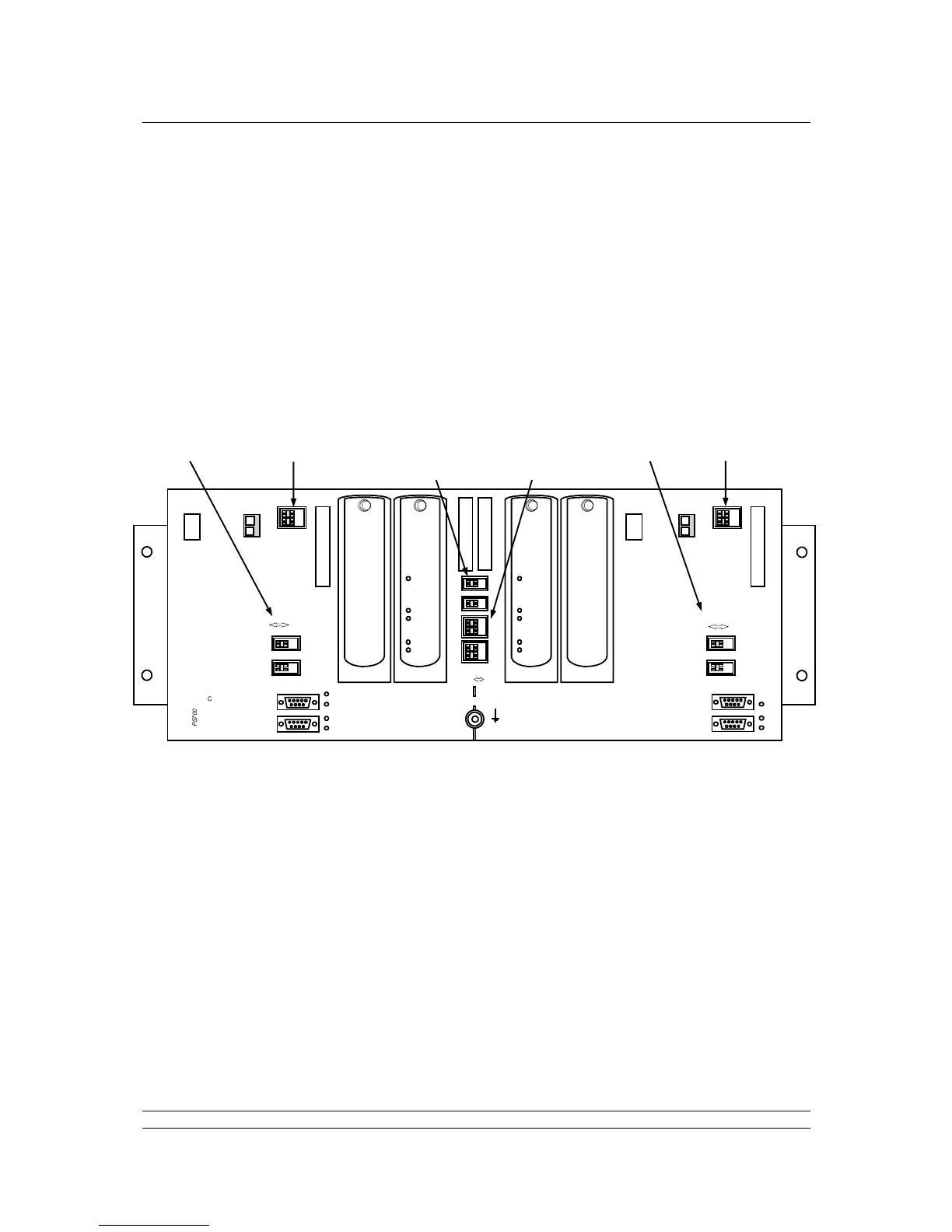
The chassis has DIP switches behind the PS710 CPU module for setting the type of serial port that is
presented at the port connectors.
Fig 25: Pakscan P3 Chassis, CPU and Key Switch modules removed
The switches on the backplane behind the PS710 CPU Module are used to set Port 1 and Port 2
parameters.
To access the switches, you will need to remove the modules shown above from the backplane.
To do this, power-off the master station completely from any power sources, either mains or DC. Then
unscrew the hex head bolt from the top of the module using the 2mm ball driver tool supplied with the
master station. Once the screw is removed, or loosened sufficiently, the module may be carefully
pulled forward at the top until the lower claws of the module can be unhooked from the slots in the
backplane.
If any plugs are left in the power sockets or serial sockets, these may prevent you from tipping the
module forward sufficiently to unhook it from the backplane.
Replacement of the module is the opposite of removal, being careful to align the module and
backplane connectors.