1. Mounting and Connecting the Master Station
Issue 06/15 Publication PUB059-002-00 21 of 136
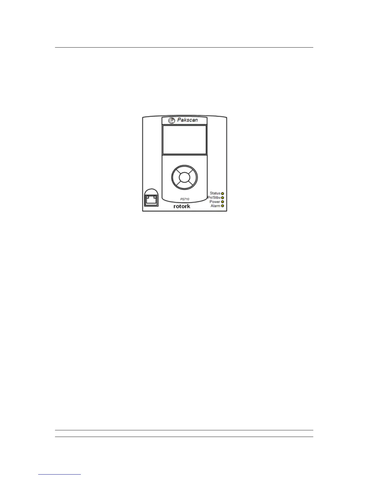
1.12 Front Panel LEDs
There are four Light Emitting Diodes (LEDs) on the front panel of the CPU module, in the bottom right-
hand corner. These are fitted to show if a unit is powered-up, which unit is in Primary or Standby mode
and whether there are any errors or alarms.
On power-up, there is a sequence of colour changes and flashes from the LEDs, which take almost a
minute to complete and confirms that all parts of the system are operating correctly:
The Status LED sequence is: off > amber > flashing green > steady green.
The Pri/Stdby LED sequence is: off > green > off > amber > steady green (amber for standby).
The Power LED sequence is: off > amber > green > green > steady green.
The Alarm LED sequence is: off > red > off > red > off.
The Status LED will show steady red if communications with the host is lost over Ethernet, or there is
a communications error between the master station and a field unit. The LED shows flashing green
only during the power-up sequence. The LED shows steady green to confirm that all applications are
running after power-up is completed.
The Pri/Stdby LED will show steady green if it is a single unit or if it is the Primary unit of a hot standby
pair. The LED will show steady amber if it is the Standby unit in a hot standby pair.
The Power LED is off when there is no power and steady green when power is present. It only shows
amber during the power-up sequence.
The Alarm LED will show steady red if there are any alarm conditions in any field unit or the master
station. This alarm will not prevent operation of the master station.
 Loading...