2. The Field Current Loop Network
Issue 06/15 Publication PUB059-002-00 25 of 136
2.2 Connecting Up
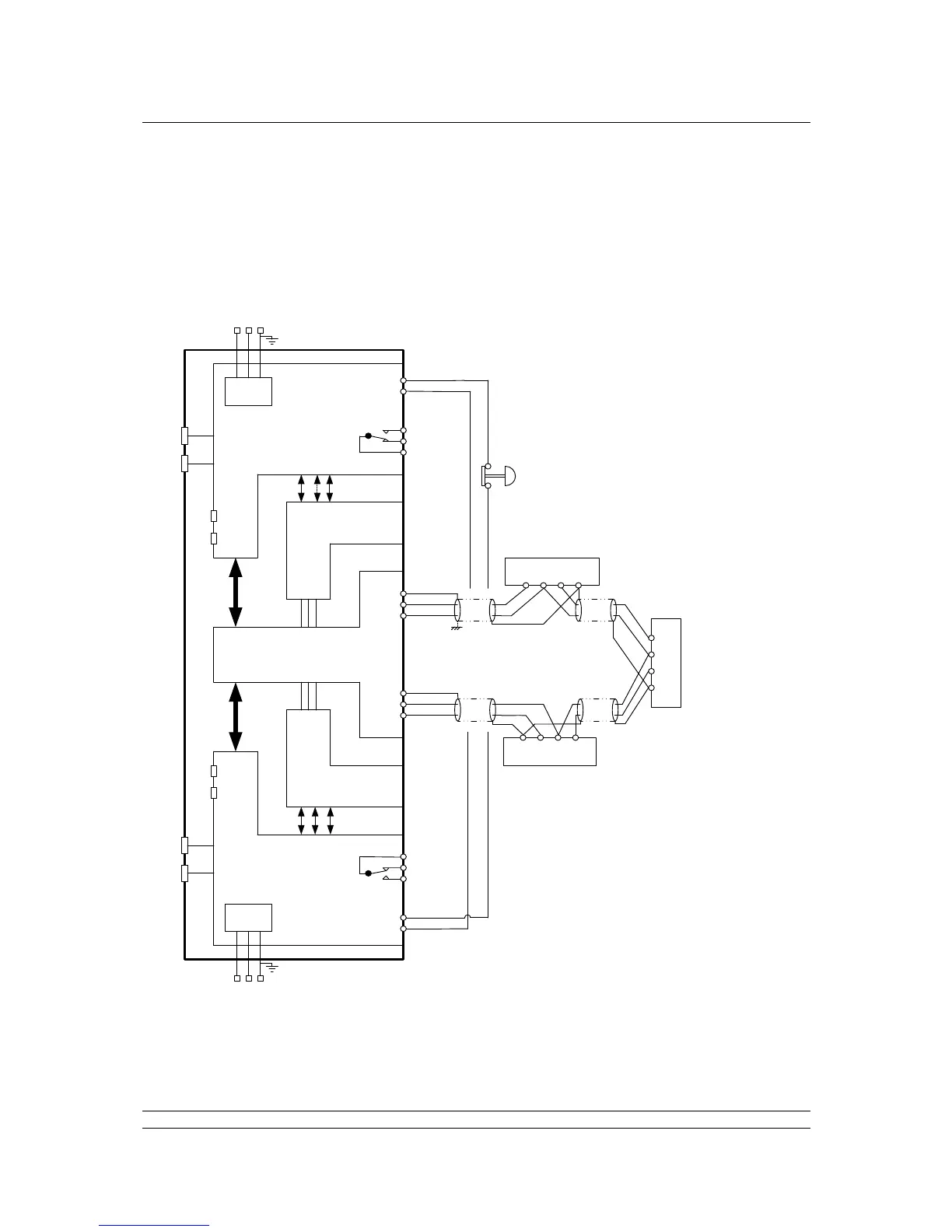
Once the checks are complete, connect the Loop Cables to the PS730 Key switch module on a hot
standby system or the PS720 Current Loop module on a single system. The Pakscan loop should
look like the figure below. Check the loop wiring complies with this drawing and then proceed to
Section 8.1 for commissioning instructions.
Note: If there is no hard-wired ESD requirement a shorting link must be fitted across pins 4 and
5 on both side A and side B of the PS710 modules.
POWER
SUPPLY
POWER
SUPPLY
MAINS
SUPPLY
MAINS
SUPPLY
L N E
L N
E
PORT 1
PORT 3
PORT 2
PORT 4
PORT 1
PORT 2
PORT 3
PORT 4
1
2
3
4
5
4
5
6
1
2
3
1
2
3
4
5
SCR
Actuator Terminals
Actuator Terminals
Actuator Terminals
B C A
SCR
A
C B
A
C
B SCR
ALARM
EMERGENCY
SHUTDOWN
WIRE A SIDE EMERGENCY
SHUTDOWN IN SERIES WITH B SIDE
Note: 4 and 5 swap over
ALARM
Screen
Screen
Port A OUT
Port A IN
Port B OUT
Port B IN
PS710 MODULE
(PROCESSORS
AND DISPLAY)
PS710 MODULE
(PROCESSORS
AND DISPLAY)
P3 MASTER
STATION ‘A’
P3 MASTER
STATION ‘B’
PS720 MODULE
(CURRENT LOOP
CONTROLLER)
PS720 MODULE
(CURRENT LOOP
CONTROLLER)
PS730
KEY SWITCH
MODULE
SIGNAL EARTH BAR
If there is a signal earth bar,
connect the screen on one side only
to the bar.
Either connect cable
screen to terminals 3 & 6
OR to signal earth bar, but
not to both.