P3 - Pakscan Master Station Technical Manual
32 of 136 Publication PUB059-002-00 Issue 06/15
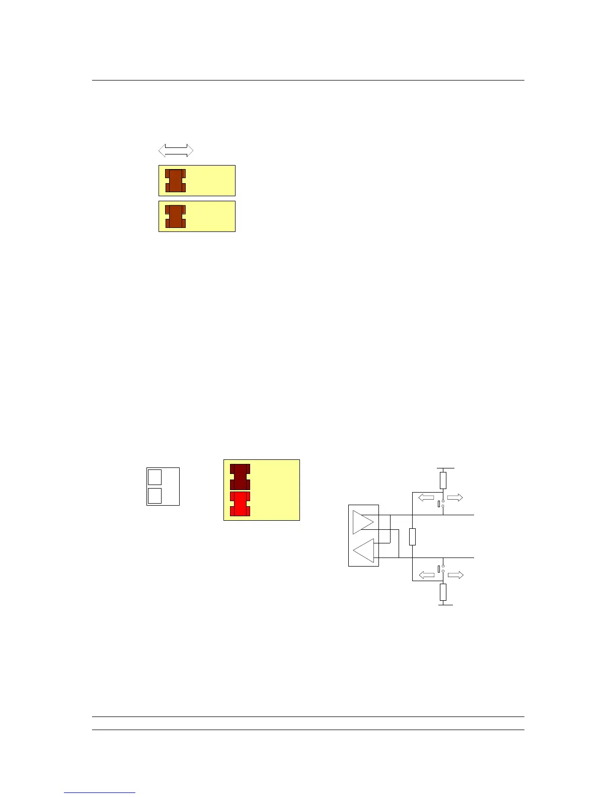
Port Function
Two DIP switches allow each port to be selected between RS-
232 and RS-485. For RS-485 slide the appropriate Port
switches to the right, for RS-232 they should be on the left.
Each of the two ports may be set independently.
Fig 26: Port Function Switches shown in RS-232 position
RS-485 Termination Resistors
Two DIP switches are used to connect end-of-line termination and biasing resistors to the RS-485
highway. All RS-485 network highways must be terminated at both ends of the highway, in this case,
at the host controller and at the master station. Only RS-485 highways need termination and biasing
resistors. If a CPU port is configured for RS-232, it must never be terminated. Each port can be
terminated independently.
Each CPU module serial port sits on an independent highway and should be terminated
independently. So, if ports 1 & 2 on a CPU module are both being used for redundant RS-485
communications to a Host controller, then each port may need to be terminated and biased.
However, where more than one CPU Module sits on the same RS-485 highway, then only the one
furthest from the host controller needs the biasing and termination resistors to be enabled.