EasyManua.ls Logo

rotork p3 - Alarm and Hardwired ESD Connector; Current Loop Connections; Fig 11: PS710 CPU Module Connector Terminal Functions; Fig 12: PS720;PS730;PS731;PS732 Current Loop Connections

rotork p3
136 pages
Print Icon
To Next Page IconTo Next Page
To Previous Page IconTo Previous Page
Loading...
1. Mounting and Connecting the Master Station
Issue 06/15 Publication PUB059-002-00 13 of 136
Port A OUT
Port A IN
Screen
Port B OUT
Port B IN
Screen
5
4
6
2
1
3
PS720/PS730
CONNECTOR
Source A
Source B
Alarm
5
4
1
2
3
Emergency
Shutdown
PS710
CONNECTOR
For the 24V DC version, a three pin removable screw terminal connector is provided. There is no
internal fuse.
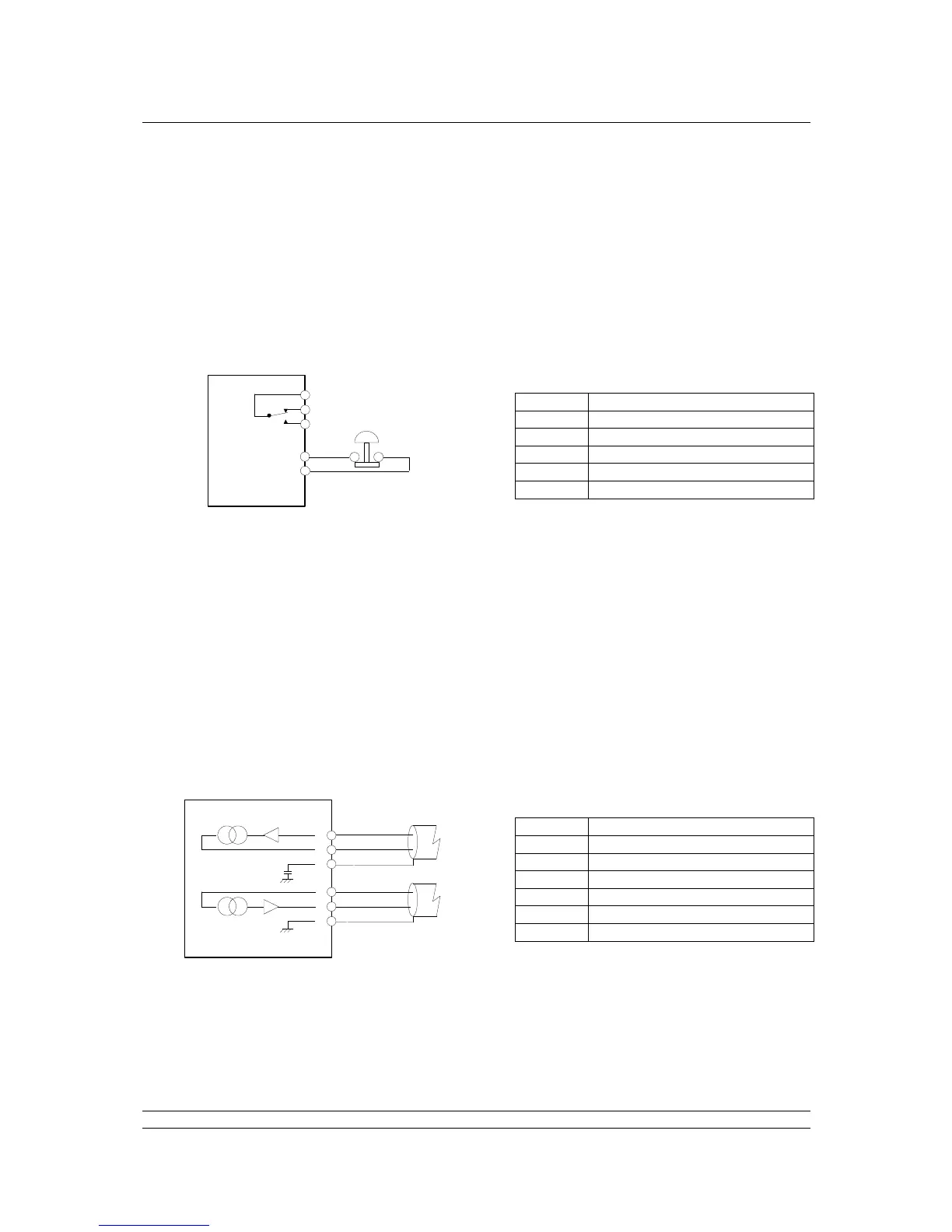
1.5 Alarm and Hardwired ESD Connector
There is a removable screw terminal connector in each Pakscan P3 CPU module for the connection of
ESD hard-wired inputs and for connection to the internal alarm relay contacts, when required. On most
systems these terminals will not be used; in which case a hard-wired link between pins 4 and 5 must
be fitted, this is usually fitted by the factory.
Note the relay is shown in the ‘alarm active’ or ‘power removed’ position. The Alarm relay will activate
if there are any alarm conditions in any field unit or the master station. This alarm will not prevent
operation of the master station.
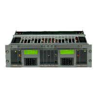
1.6 Current Loop Connections
A connector is located in the bottom of the key switch module on hot standby Pakscan 3 systems for
the connection of the current loop to the field mounted actuators. On single P3 master stations the
connector beneath the current loop module itself should be used.
Terminal
Function
1
Alarm (common)
2
Alarm (normally closed)
3
Alarm (normally open)
4
Emergency Shutdown
5
Emergency Shutdown
Terminal
Function
1
Port B In
2
Port B Out
3
Port B Screen
4
Port A In
5
Port A Out
6
Port A Screen
Port A OUT
Port A IN
Screen
Port B OUT
Port B IN
Screen
5
4
6
2
1
3
PS720/PS730
CONNECTOR
Source A
Source B
Alarm
5
4
1
2
3
Emergency
Shutdown
PS710
CONNECTOR
Fig 11: PS710 CPU module connector terminal functions
Fig 12: PS720/PS730/PS731/PS732 Current Loop connections

Table of Contents

Related product manuals