1. Mounting and Connecting the Master Station
Issue 06/15 Publication PUB059-002-00 15 of 136
1.8 P3W Repeater and P3W WMA AC Power Connections
The P3W Repeater AC and the P3W WMA AC will contain a power module for the appropriate power
supply requested by the user. The power module is mounted the base half of the module with the
wireless module in the other half, the modules will be connected together by an interconnecting loom,
connected to SK1 on the power module and SK3A on the wireless module. The mains AC
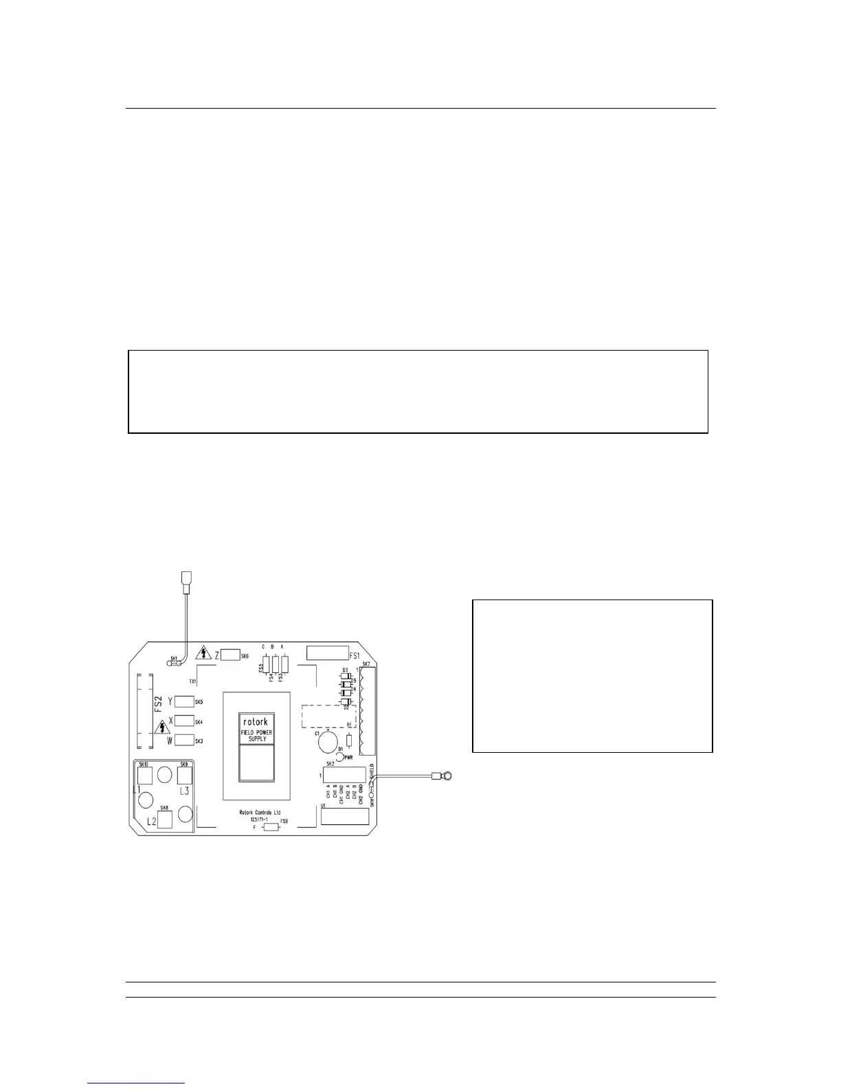
connections are made to the power module connections L1, L2 and L3, shown in the Figure below.
The mains cable will need to be terminated in 4 mm ring crimps.
SK1, a flying lead, will be fitted by the factory to the appropriate tapping for the power supply that the
customer has indicated will be used. Fitting to the posts labelled W, X, Y and Z selects the correct
voltage. This should be checked for correct fitment before power is applied.
A switch or circuit breaker must be included in the wiring installations. The switch or circuit breaker
must be mounted as close to the module as possible and shall be marked to indicate that it is the
disconnect device for that particular module. The Power cable and appropriate glands for the P3W
coordinator will need to be sourced locally, according to site requirements.
Power supply: 3 Phase up to nominal 690V, 50 or 60Hz or
Single Phase up to nominal 230V, 50 or 60 Hz.
Check that the supply voltage agrees with that stated on the nameplate.
Power should only be applied with the module fully assembled i.e. the base
and the cover connected together with the bolts supplied.
Cable glands used must be appropriate to the classification of the area.
Conduit seals must be installed at the enclosure.
SK2 is the Modbus connection.
U1 is the cable screen clamp.
SK7 is the loom for the Wireless pcb.
FS1 is a 250 mA S500 fuse.
FS2 is a 100mA TDC11 fuse.
The wire attached to SK11 should be
attached by one of the pcb mounting
screws to the casing.