4. Configuring Serial Communications
Issue 06/15 Publication PUB059-002-00 33 of 136
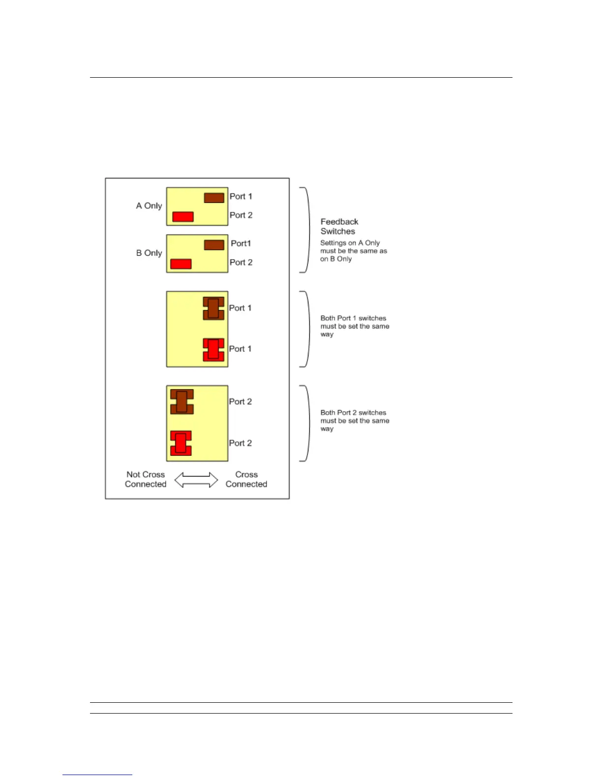
Cross Connection switches
The cross connection switches, found on the backplane behind the PS710 CPU Module, are used to
cross connect the serial RS-485 connections. They are only applicable for a hot standby system and
should ONLY be set as cross connected for a port that has been selected as RS-485.
Fig 28: Cross connection switch settings on the backplane behind the Switch Module
The switches are shown in the Factory Default positions (Hot Standby).
Port 1 is set to Cross-Connected for RS-485 Serial communications. Port 2 is set to Not Cross-
Connected for RS-232 Serial Communications.
The feedback switch positions must reflect the Cross-Connection settings for Port 1 and Port 2.
These switches are used, by the master station CPU, to indicate to the user (via the HMI or web
pages) the position of the cross-connect switches.