Section 11 ELECTRICAL CONNECTORS AND WIRING DIAGRAMS
Subsection 01 (ELECTRICAL CONNECTORS)
1
V01G0OA
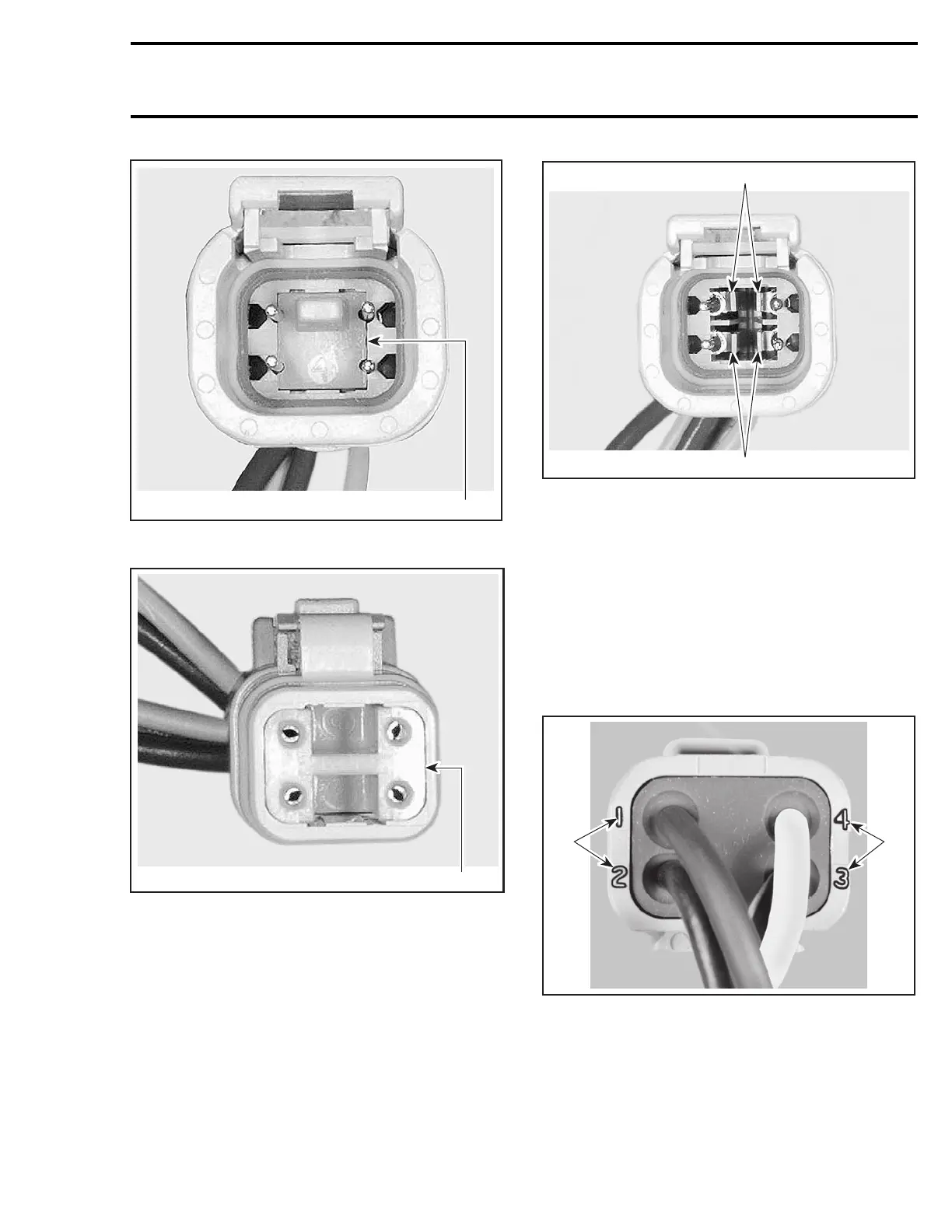
FEMALE CONNECTOR
1. Female lock
V01G0PA
1
MALE CONNECTOR
1. Male lock
NOTE: Before extraction, push wire forward to
relieve pressure on retaining tab.
– Insert a 4.8 mm (.189 in) wide screwdriver blade
inside the front of the terminal cavity.
– Pry back the retaining tab while gently pulling
wire back until terminal is removed.
V01G0QA
1
1
FEMALE CONNECTOR
1. Retaining tab
To install:
– For insertion of a terminal, make sure the lock
is removed.
– Insert terminal into appropriate cavity and push
asfarasitwillgo.
– Pull back on the terminal wire to be sure the
retention fingers are holding the terminal.
– After all required terminals have been inserted,
the lock must be installed.
F04H6LA
1 1
1. Wire identification numbers
smr2005-026 297
 Loading...


