CDHD Application Setup
User Manual 147
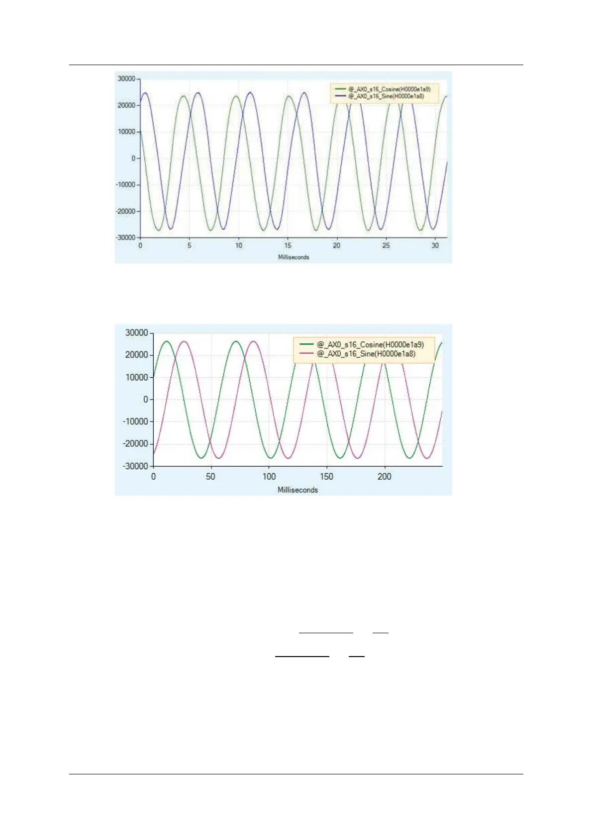
Figur e 6 - 1 2 . Ex am ple of Sin e Encoder Recor ding
A typical recording of resolver might look as shown in Figure 6-13:
Figur e 6 - 1 3 . Ex a m ple of Re solve r Recording
Con ve r t in g t o Ph ysical Value s
The recorded dat a is in internal drive units, and needs to be convert ed to
physical units; that is, the input volta ge t o the drive.
Since the physical sine and cosine signals are scaled differently for the sine
encoder and the resolver, the following equations are used t o convert the
recorded data:
Sine encoder : Input Voltage =
Recorded Value
32768
×
10
16.2
Resolver: Input Voltage =
Recorded Value
32768
×
10
3.25
Exa m ining the Plot
The recorded dat a can be scaled in the ServoStudio Scope screen.
When exam ining the sine and cosine signals from a sine encoder, you need t o
multiply the signals by 0.00001883 (calculated from 1/32768 x 10/16.2)