Tuning CDHD
216 User Manual
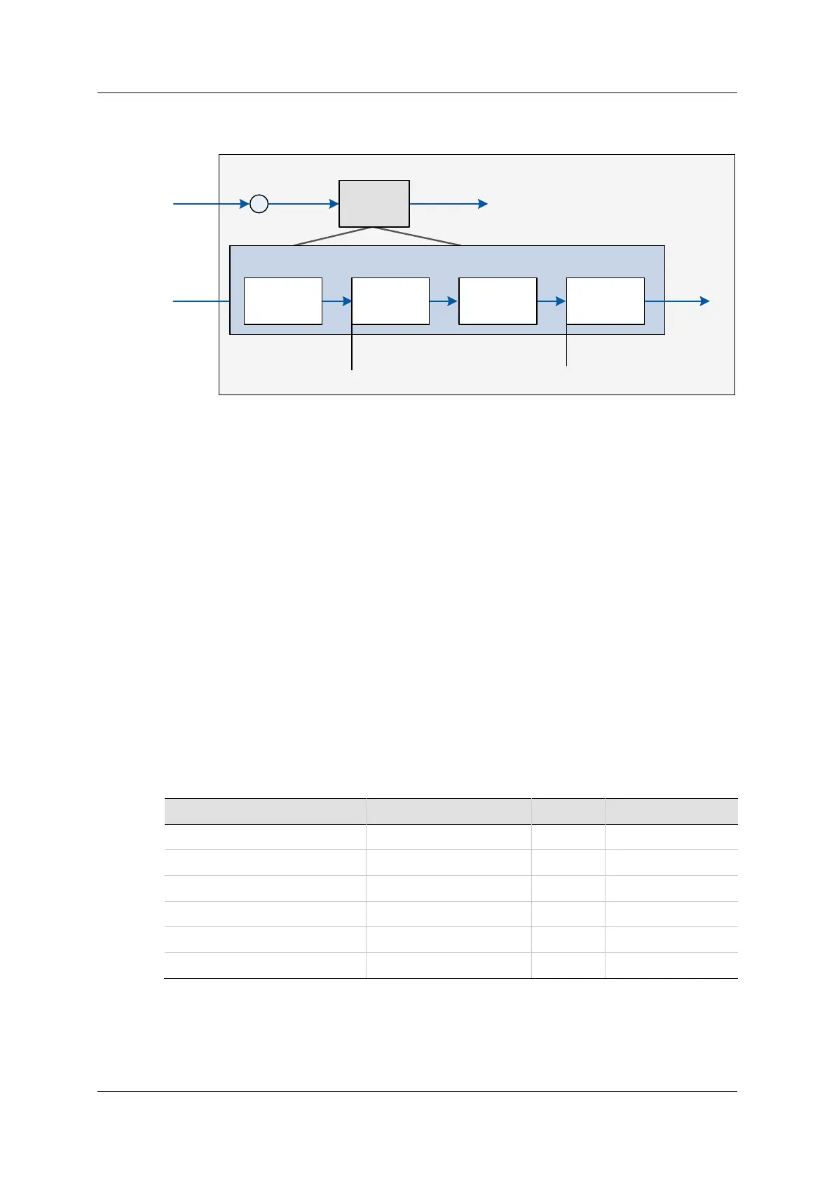
The following diagram shows the four phases of the vibration suppression
process.
Figur e 9 - 2 7 . Ant i- Vibra t ion Filter s
Phase 1 : The perturbations induced to the system are detected using various
control variables, such as position error and current, as input. A perturbation
value is calculated for use in the next phase.
Phase 2 : The perturbation value is passed through a narrow band pass filter in
order to select the perturbations that are induced by the system oscillations. The
cent er frequency and the widt h of the band pass filter are set, respectively, by
t he paramet ers N LANTI VI BHZn and N LANTI VI BSHARPn .
Phase 3 : Corrective outputs to be added to the control variables are calculated.
Phase 4 : Corrective outputs are added to control variables using a damping gain
(param eter NLAN TI VI BGAI Nn ) .
Ant i- Vibra tion Tuning Procedure
After autotuning, m ore ant i-vibration tuning m ay be required.
I f an additional vibration frequency needs to be suppressed, the turning process
can be repeated using t he second set of anti-vibration filters.
The following t able shows the parameters whose values are modified by the
HD tuning procedures.
HD Ant i- Vibra t ion Filt er Param eter D e fault Range
Cent er Fr equency 2 N LAN TI VI BHZ2 1 0 0 5 to 8 0 0 [ H z]
Center Frequency 3 NLANTI VI BHZ3 400 5 to 800 [ Hz]
Sharpness 2 N LAN TI VI BSH ARP2 0 .5 0 .0 1 t o 1 0
Sharpness 3 NLANTI VIBSHARP3 0.2 0.01 to 10
Dam ping Ga in 2 N LAN TI VI BGAI N 2 0 0 to 9 9
Damping Gain 3 NLANTI VI BGAI N3 0 0 t o 6
N ote: Although parameters NLANTIVBHZ, NLANTI VIBSHARP and
NLANTIVIBGAIN are still available, they are not recom mended for use.
PE
Current
Command
Position
Command
Σ
Control
Variables
Corrected
Control
Variables
HD Control
Loop
Anti-Vibration Algorithms
Center Frequency - NLANTIVIBHZn
Sharpness - NLANTIVIBSHARPn
Gain - NLANTIVIBGAINn
Detect
Perturbation
Narrow Band
Pass Filter
Corrective
Outputs
Perturbations
Damping Gain
parameters
 Loading...

