CDHD Tuning
User Manual 217
St e p 1 – Se t t ing the Narrow Band Filter ( NBF)
1 . Set the narrow band cent e r frequency.
Execute a movement and measure the resonance (oscillation frequency)
of the current comm and (I CMD):
In the Scope screen, right-click on the I CMD plot.
Select FFT a nd De r ivat ive .
Select FFT Tra ce .
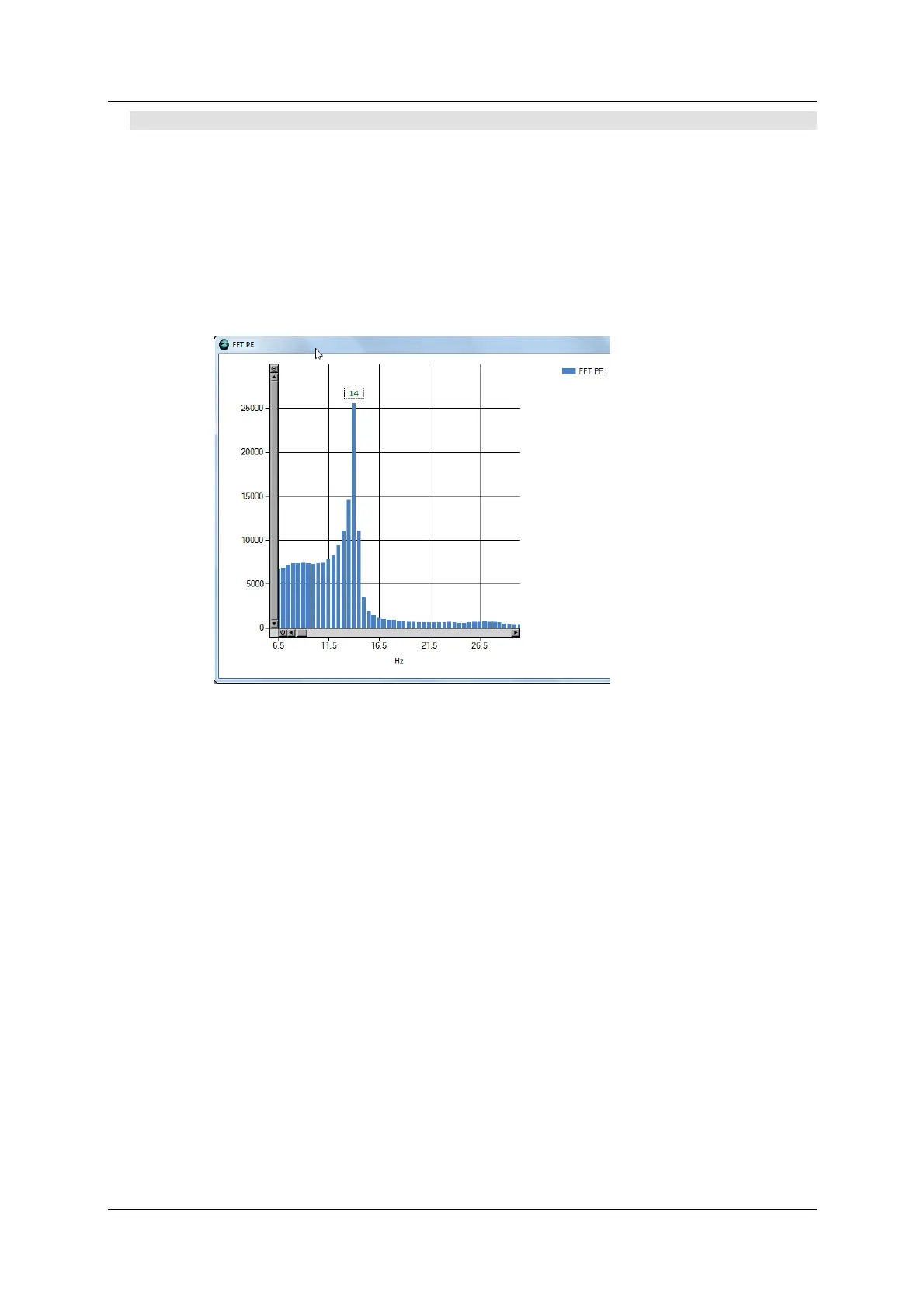
The FFT trace will look like this, for exam ple:
Figure 9 - 2 8 . FFT Trace
Set the value of param eter NLANTIVIBHZn to the peak, or dom inant ,
resonance, in Hert z. In the exam ple shown here, the value is 14 Hz.
2 . Set the narrow band cent e r sharpness ( w idth) .
Set the value of param eter NLANTIVIBSHARPn according to the
resonance sharpness (width) of the narrow band filter.
Estim ate the width by visually com paring the graph in the FF Trace
dialog box to the graph below, which shows the frequency response of
the NBF as a function of the value of NLANTIVI BSHARPn. Typical setting
values range from 0.1 to 1.0.
The following diagram shows the narrow band filter frequency response.
 Loading...

