Appendix
A.2 I/O Connections and Wiring
FUS1010 IP65 NEMA 4X & IP66 NEMA 7
200 Operating Instructions, 01/2013, A5E02951520-AC
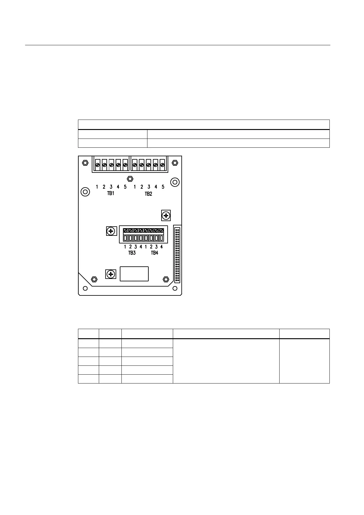
Terminal Block Wiring - 7ME39400SA00 - Analog Input Module - Single Channel
(Refer to manual drawing 1010N-5S2-7)
These connection diagrams apply to the part numbers listed below.
Table A- 20 Connection Diagrams and Part Numbers
1010N-5S2-7 Drawing
FUS1010 7ME3530, 7ME3533
FUH1010 7ME3600, 7ME3603
Figure A-6 7ME39400SA00 - Analog Input Module
Table A- 21 Input/Output Wiring TB1 7ME39400SA00 - Analog Input Module
Pin Color Function Description Wiring/Cable
TB1-1 Black RTD Current High
TB1-2 White RTD Voltage High
TB1-3 Green RTD Voltage Low
TB1-4 Red RTD Current Low
TB1-5 Blue Ground
RTD Temperature measurement T1 or
Channel 1 Ts (Supply Temperature)
AWG. 14 - 24 /
1000 Ft max w/o
factory approval