Description
3.4 Theory of Operation
FUS1010 IP65 NEMA 4X & IP66 NEMA 7
Operating Instructions, 01/2013, A5E02951520-AC
25
R
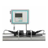
① Velocity of Sound
② Flow Vector
③ Pipe ID
④ WideBeam Sensors
∅= sin
1
(VOS / V
phase
) Where: VOS = Velocity of sound in liquid
V
phase
= Phase velocity of sensor
T
L
= 2 * ID / (VOS * cos ∅) ID = Pipe inside diameter
T
L
= Transit time in liquid
V
F
= V
phase
* DT / (2 * TL) DT = Measured Transit-Time difference
V
F
= Flow Velocity
Flow Profile Compensation
The flow equation shown above is only valid for "plug" flow, where the flow velocity is
uniform across the entire cross-section of the pipe. Frictional forces between the fluid and
the pipe wall cause the flow velocity to be nearly zero at the pipe wall and peaked toward the
center of the pipe (as shown in the diagram below).
The acoustic beam traverses the center of the pipe and therefore must account for the
influence that flow profile has on the line integration through a round pipe. The shape of this
flow profile (for fully developed flow) is defined by the Reynolds number.

 Loading...


