Connecting
5.5 Sensor Installation
FUS1010 IP65 NEMA 4X & IP66 NEMA 7
72 Operating Instructions, 01/2013, A5E02951520-AC
Installing a 1012T Mounting Track in Direct Mode
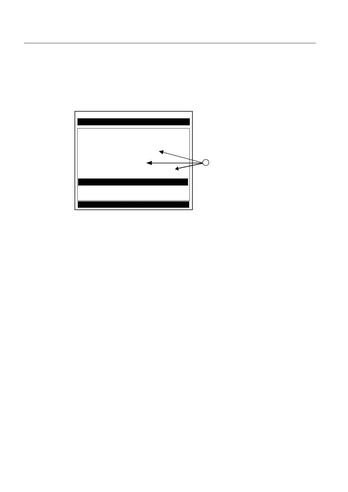
The Sensor Installation procedures show how the automatic selection of sensors, mounting
mode and spacing method are established. Examine the figure below, which illustrates a
typical [Install Sensor] menu screen. Note the automatic assignment of model numbers for
the sensor and mounting track, plus the designation of the number index.
6LHPHQV 'XDO3DWK>@ 6,7(
,QVWDOO&RPSOHWH"
,QVWDOO6HQVRU
,QVWDOO3DWK
6HQVRU0RGHO +37
6HQVRU6L]H %
6HQVRU0RXQW0RGH 'LUHFW
6SDFLQJ2IIVHW0LQLPXP
1XPEHU,QGH[
6SDFLQJ0HWKRG7UDFN71
/WQ9DOXHLQ
(PSW\3LSH6HW &KDQQHO1RW6HWXS
=HUR)ORZ$GMXVW &KDQQHO1RW6HWXS
,QVWDOO&RPSOHWH 1R
① Automatic selection of mounting track part number , mount mode and number index
The combination of two Model 1012TN Mounting Tracks and a spacer guide is the
recommended way to mount sensors in the Direct Mode. This method ensures that sensors
will align exactly 180° from each other and remain spaced the proper distance apart.
The Direct Mount configuration uses a set of two track rail assemblies; one for each sensor,
installed 180° apart on the pipe. The set includes:
● Reflect Mode Track Assembly - This track rail includes the Tension Screw and REF hole
to position one sensor.
● Direct Mode Track Assembly - This track rail has number index holes for inserting an
index pin to position the other sensor.