9.7.10 Step 4 - Configuring the setpoint default
Prerequisites
● Graphics Designer is open.
● The block icon for "SP_INT_EXT" is available.
Procedure
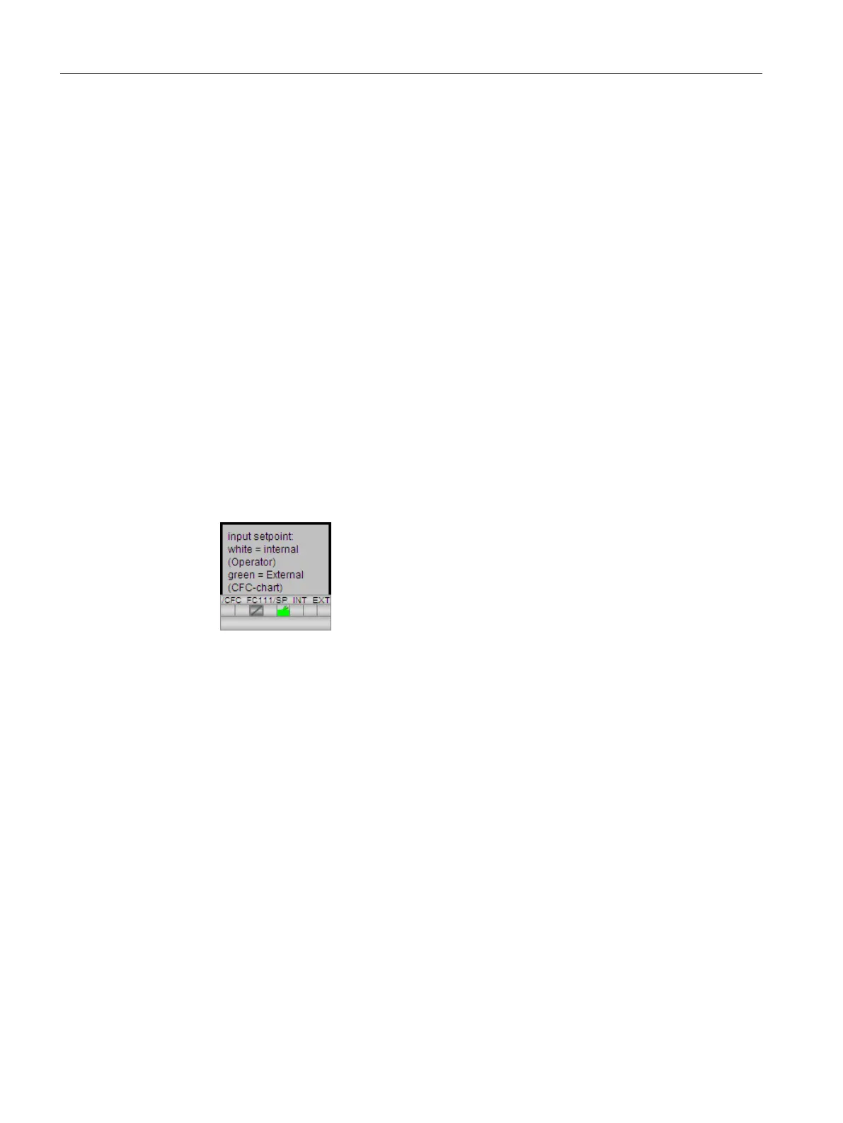
1. Insert an explanatory text field: "Input setpoint, white = internal (operator), green = external
(CFC-chart)".
2. Format the text field using the style palette:
– Frame: invisible – "Line Weight/Invisible" setting
– Fill: Transparent – "Fill Pattern/Transparent" setting
3. Insert a whole frame from the object palette: "Standard Objects/ Rectangle" object.
4. Format the whole frame using the style palette:
– Line weight of frame -- "Line Weight/3 Pixel" setting
– Fill: Transparent – "Fill Pattern/Transparent" setting
5. Position the block icon for "SP_INT_EXT" under the frame.
6. Position the grouped objects in the lower section on the left side.
Configuring the operator station
9.7 Creating the process picture
PCS 7 SMART Getting Started - Part 1 (V9.0 with APL)
168 Getting Started, 12/2017, A5E42181435-AA