Note on the Display
Note
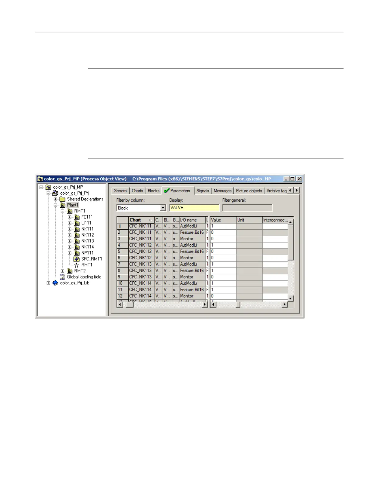
Depending on the size of your monitor, you may not be able to see the "Chart" column any
more and, as a result, the assignment of the individual I/Os to a chart becomes difficult.
The process object view offers you the following options:
1. Position the cursor on the small box on the left next to the horizontal scroll bar and click.
This makes a vertical marker visible in the table.
2. Hold down the mouse button and drag this vertical marker behind the "I/O" column.
3. Release the mouse button.
This splits the table window and you can navigate in the right side with the horizontal scroll
bar in the table, while the chart names are displayed on the left side.
6.7.2.4 Deleting Interconnections to addresses
Introduction
You can use process tag types from the PCS 7 AP Library in your project for the NK111 to
NK114 valve controls and the NP111 motor control. These process tag types have default
interconnections to input/output modules. Because you are working without real input/output
modules in this Getting Started, a warning message appears during compilation. You have to
delete these interconnections to avoid the warnings.
Creating CFCs
6.7 CFCs in the process object view
PCS 7 SMART Getting Started - Part 1 (V9.0 with APL)
Getting Started, 12/2017, A5E42181435-AA 103