Procedure
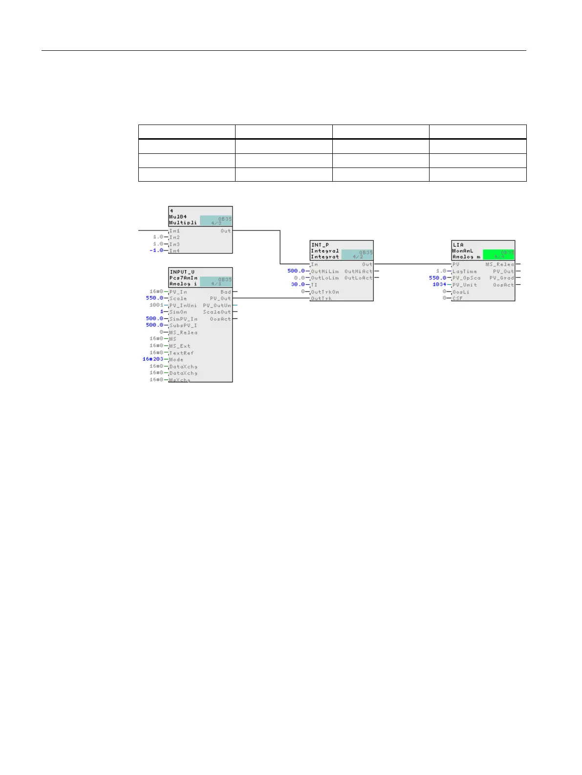
1. Interconnect the blocks according to the table below.
Block description Output Block description Input
INPUT_U PV_Out INT_P OutTrk
INT_P Out LIA PV
4 Out INT_P In
2. The CFC should now appear as follows:
3. Close the chart.
6.6.18 Assigning parameters for the blocks in "Valve_Lean"
In PCS 7 SMART, you can prepare process tag types for the specific plant.
Prerequisites
The "Valve_Lean" CFC chart is open in the CFC Editor - saved in the "color_gs_prj_Lib\Process
tag types\Valve_Lean" folder.
Creating CFCs
6.6 Working with the CFC Editor
PCS 7 SMART Getting Started - Part 1 (V9.0 with APL)
96 Getting Started, 12/2017, A5E42181435-AA