6.6.16 Interconnecting blocks in the "CFC_FC111"
Prerequisites
● The "CFC_FC111" CFC is open in the CFC Editor.
● All blocks are inserted, renamed and configured.
Procedure
1. Click the "Out" output on the "SP_INT_EXT" block.
2. Now click the "SP_LiOp" input on the "DOSE" block.
The CFC Editor automatically creates a line indicating the interconnection.
3. Following the same procedure, interconnect additional blocks according to the table below.
(The "4" block is located on the CFC_LI111 chart. To do this, place the two charts side by
side.)
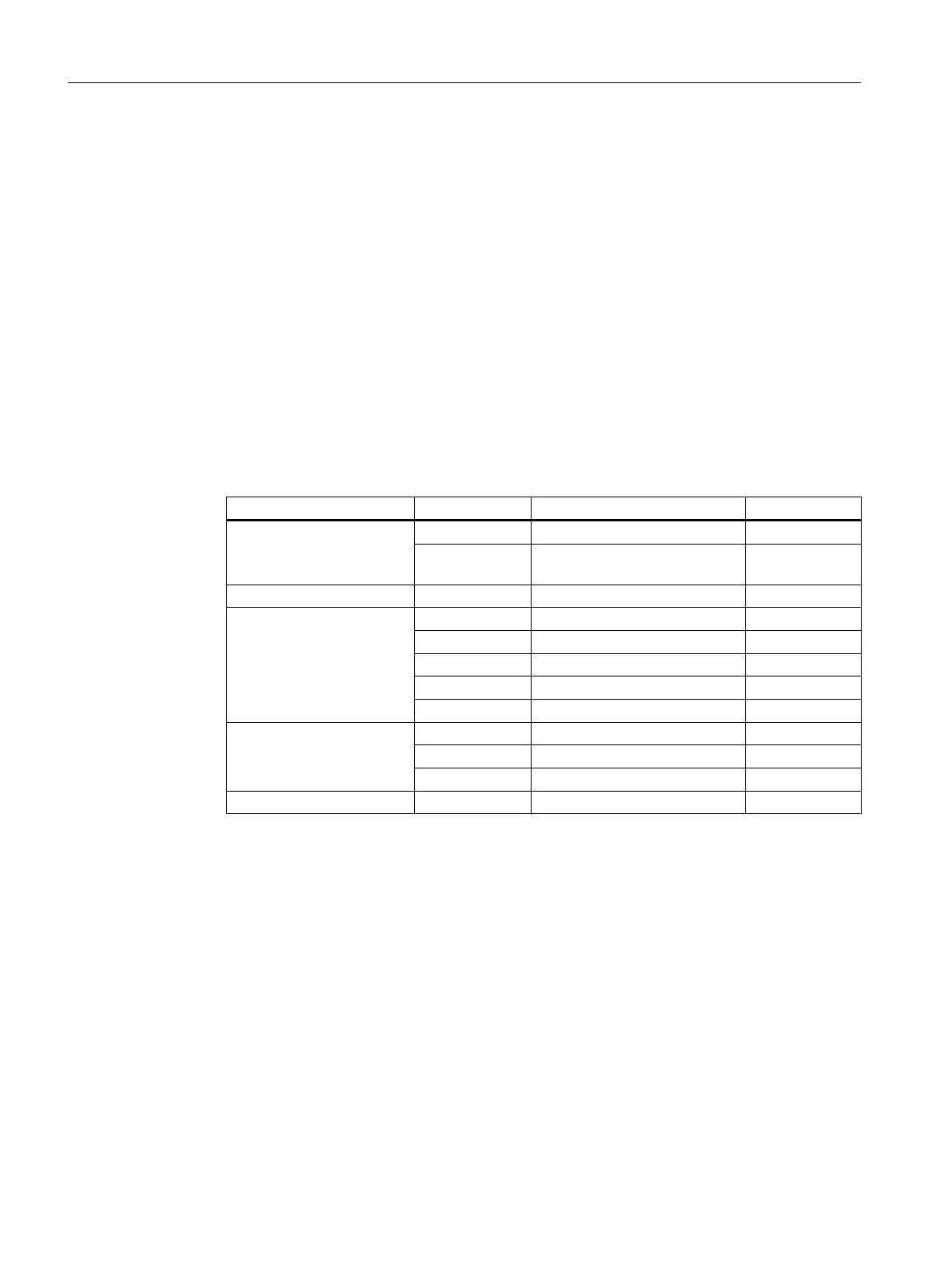
Block description Output Block description Input
SP_INT_EXT Out DOSE SP_ExtLi
Out DOSE SP_IntLi (Inver‐
ted)
DOSE SP CTRL_PID MV_TRK
INPUT_U PV_Out DOSE PV
PV_Out CTRL_PID PV
PV_Out 4 (in chart CFC_LI111) In1
PV_OutUnit DOSE PV_Unit
PV_OutUnit CTRL_PID PV_Unit
CTRL_PID MV OUTPUT_LMN PV_In
MV MUL In1
SP MUL In4
MUL Out INPUT_U SimPV_In
Creating CFCs
6.6 Working with the CFC Editor
PCS 7 SMART Getting Started - Part 1 (V9.0 with APL)
94 Getting Started, 12/2017, A5E42181435-AA