Procedure
1. Open the "General" tab and "Inputs/Outputs" tab in the "Object Properties" dialog box for
each block.
– Enter the parameters for all blocks according to the table below.
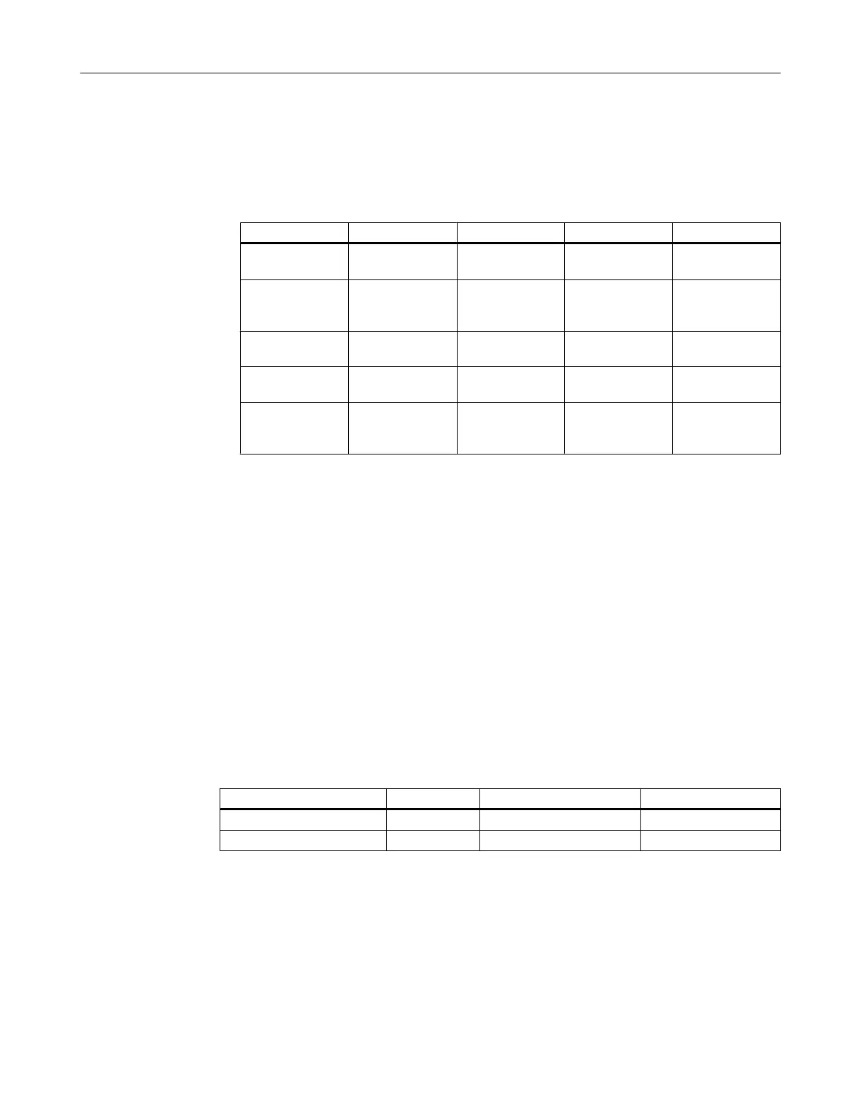
Block Name in project I/O Meaning Value
Pcs7DiIn FbkClose SimOn.Value Simulation ena‐
bled
1
Pcs7DiIn FbkClose SimPV_In.Value
(inverted after in‐
terconnection)
Simulation value
PV
0
Pcs7DiIn FbkOpen SimOn.Value Simulation ena‐
bled
1
Pcs7DiIn FbkOpen SimPV_In.Value Simulation value
PV
0
VlvL Valve Feature.Bit4 Set switch or but‐
ton mode (switch
mode)
1
– In the "General" tab, accept the default setting for "Create block icons" (no checkmark
for the blocks Interloc, Permit and Protect).
2. Click "OK" for each block. Your settings are applied.
6.6.19 Interconnecting the blocks in "Valve_Lean"
Prerequisites
● The "Valve_Lean" CFC chart is open in the CFC Editor.
● The blocks have been created in the project library and parameters are assigned.
Procedure
1. Interconnect the blocks for each chart according to the table below.
Block description I/O Block description I/O
Valve Ctrl FbkOpen SimPV_in
Valve Ctrl FbkClose SimPV_In (inverted)
2. Close the chart.
Creating CFCs
6.6 Working with the CFC Editor
PCS 7 SMART Getting Started - Part 1 (V9.0 with APL)
Getting Started, 12/2017, A5E42181435-AA 97